
Labor-saving knee rest device, sewing machine and presser foot lifting method

A presser foot lifting and presser foot technology, applied in the field of presser foot lifting and labor-saving knee rest devices, can solve the problems of labor intensity and difficult operation of the operator, and achieve high work efficiency

Inactive Publication Date: 2019-05-31
JACK SEWING MASCH CO LTD
View PDF7 Cites 2 Cited by
  • Summary
  • Abstract
  • Description
  • Claims
  • Application Information

AI Technical Summary

Problems solved by technology

[0002] At present, most lockstitch sewing machines use the knee rest device to realize the function of lifting the presser foot. On some thick-material lockstitch sewing machines, because the sewing material is too thick, the presser foot spring needs to provide a large pressing force for the presser foot assembly to work normally. The cloth feeding function is carried out, so that the knee rest device needs to overcome the large pressing force of the presser foot spring in the process of lifting the presser foot to fully lift the presser foot assembly, which makes the operator's labor intensity and operation difficult

Method used


Image

  • Labor-saving knee rest device, sewing machine and presser foot lifting method
  • Labor-saving knee rest device, sewing machine and presser foot lifting method
  • Labor-saving knee rest device, sewing machine and presser foot lifting method

Examples


Embodiment Construction

[0034] The specific implementation manners of the present invention will be described in further detail below in conjunction with the accompanying drawings. These embodiments are only used to illustrate the present invention, not to limit the present invention.

[0035] In the description of the present invention, it should be noted that the terms "center", "longitudinal", "transverse", "upper", "lower", "front", "rear", "left", "right", " The orientations or positional relationships indicated by "vertical", "horizontal", "top", "bottom", "inner", "outer", etc. are based on the orientation or positional relationships shown in the drawings, and are only for the convenience of describing the present invention and simplifying Describes, but does not indicate or imply that the device or element referred to must have a specific orientation, be constructed in a specific orientation, and operate in a specific orientation, and therefore should not be construed as limiting the inventio...


PUM


Abstract

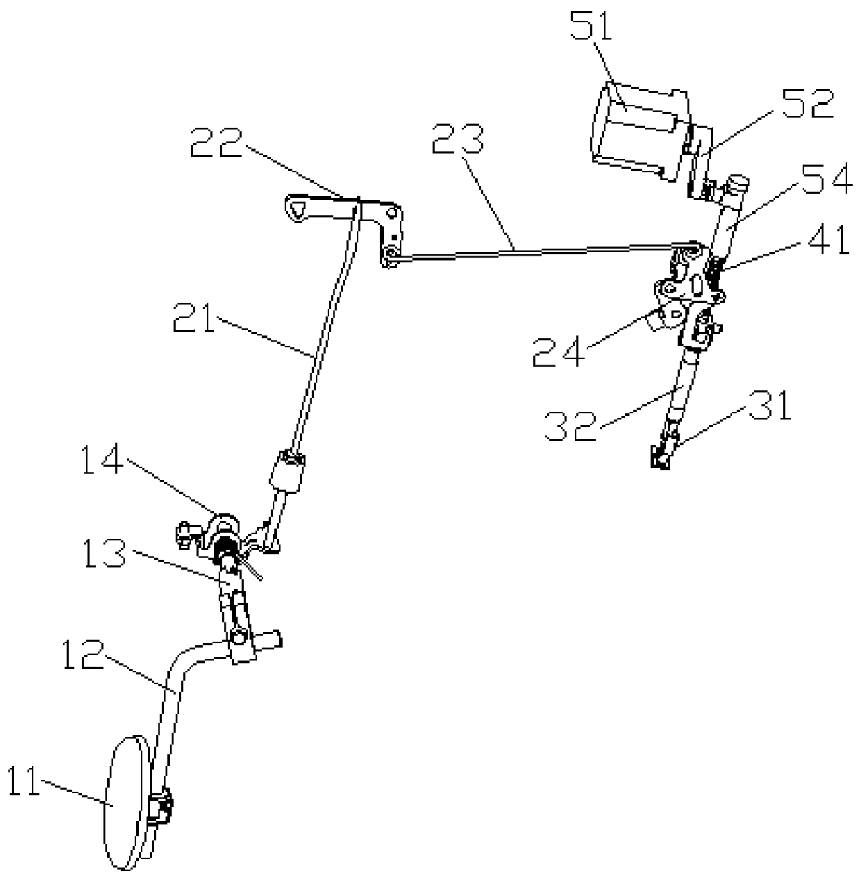
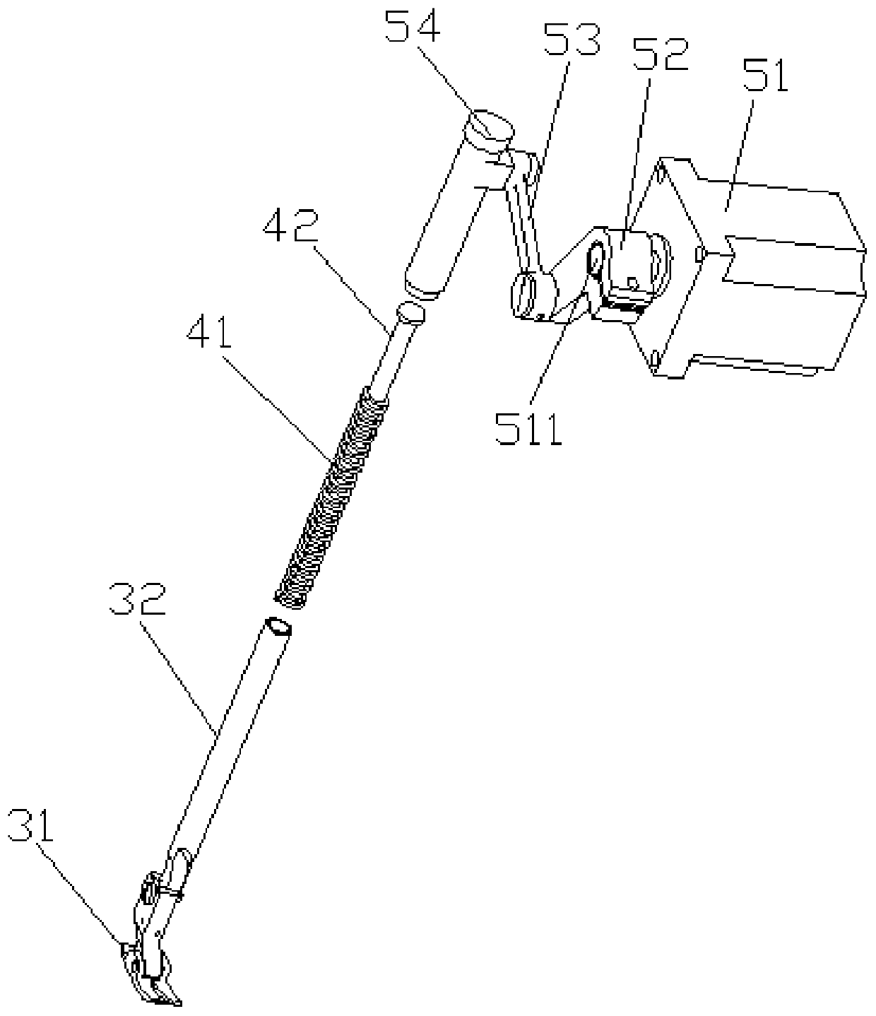
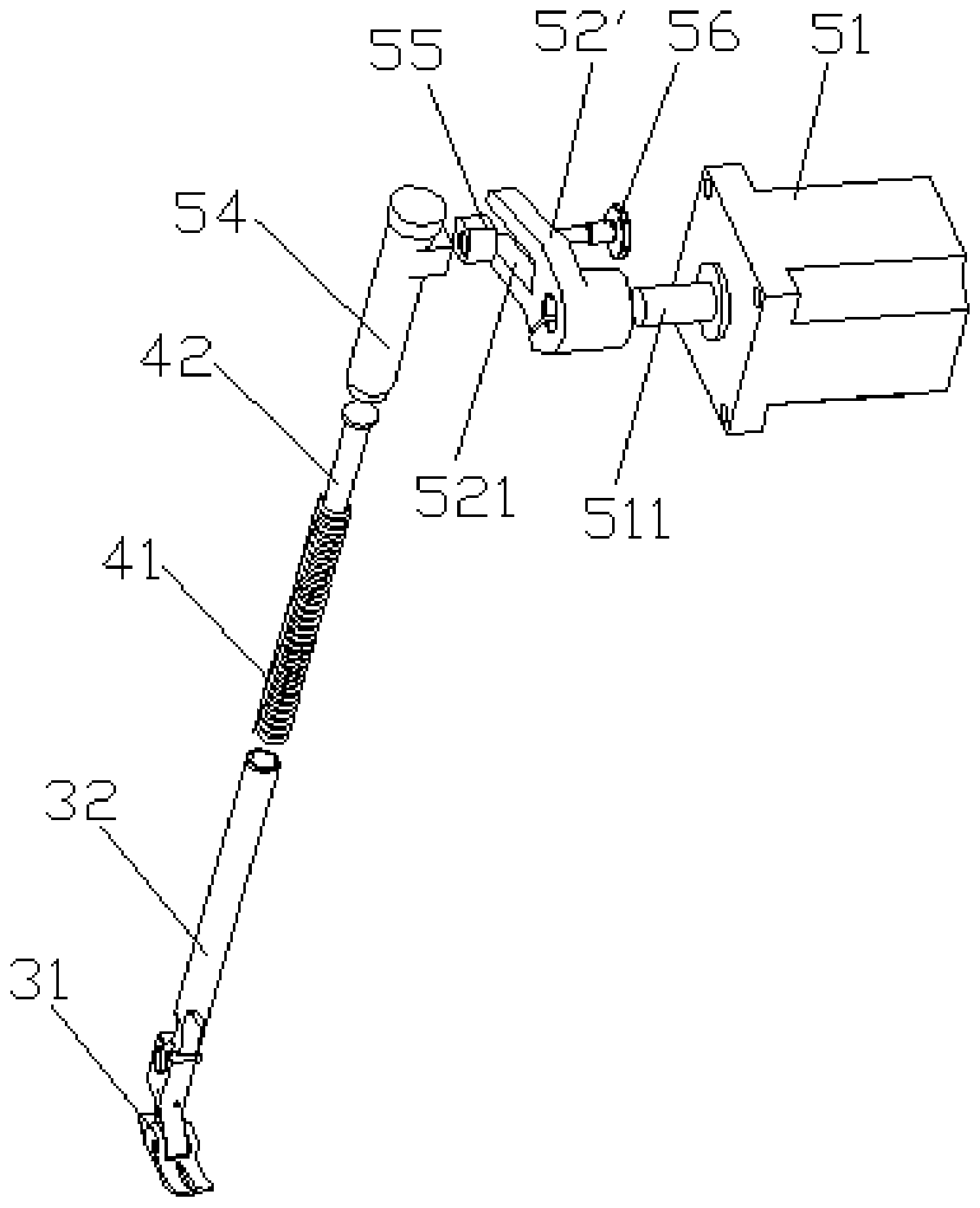
The invention relates to the technical field of sewing machines, in particular to a labor-saving knee rest device, a sewing machine including the labor-saving knee rest device and a presser foot lifting method. The labor-saving knee rest device includes a controller, a knee-rest mechanism for driving a presser foot lifting mechanism to lift a presser foot component, a sensor for detecting the position change of the knee-rest mechanism, a presser foot spring for providing the pressing force for the presser foot component, and a drive mechanism used for adjusting the compression amount of the presser foot spring. The sensor and the drive mechanism are connected with the controller, and the controller controls the drive mechanism to move according to a detection signal of the sensor. The presser foot lifting method includes the following steps that when the knee-rest mechanism is manually operated to move and drive the presser foot lifting mechanism to lift the presser foot component, thesensor detects the position change of the knee-rest mechanism and conveys the detection signal to the controller, the controller receives the detection signal and outputs an action instruction according to the detection signal, and the drive mechanism receives the action instruction and responds to the action instruction to adjust the compression amount of the presser foot spring. Labor is savedwhen lifting of the presser foot is controlled.

Description

technical field [0001] The invention relates to the technical field of sewing machines, in particular to a labor-saving knee rest device, a sewing machine including the labor-saving knee rest device and a presser foot lifting method. Background technique [0002] At present, most lockstitch sewing machines use the knee rest device to realize the function of lifting the presser foot. On some thick-material lockstitch sewing machines, because the sewing material is too thick, the presser foot spring needs to provide a large pressing force for the presser foot assembly to work normally. The cloth feeding function is performed, and thus the knee rest device needs to overcome the greater pressing force of the presser foot spring in the process of lifting the presser foot to fully lift the presser foot assembly, which makes the labor intensity and operation difficulty of the operator larger. Contents of the invention [0003] The technical problem to be solved by the present inv...

Claims


Application Information

Patent Timeline
Patent Type & Authority Applications(China)
IPC IPC(8): D05B29/02D05B69/02
Inventor 位延辉祝书伟郏彬辉柯祥林
Owner JACK SEWING MASCH CO LTD
Learn More