
Traction grass planter for desert control

A technology for desert control and lawn planter, applied in the field of desert control traction lawn planter, can solve the problems of increasing the probability of seed survival, difficult to survive grass squares, and too much artificial input, so as to improve the survival rate, walk smoothly, reduce The effect of work intensity

Pending Publication Date: 2019-05-31
佘书强
View PDF0 Cites 5 Cited by
  • Summary
  • Abstract
  • Description
  • Claims
  • Application Information

AI Technical Summary

Problems solved by technology

[0002] At present, the land desertification in the country is becoming more and more serious. People adopt various methods to fix and control sand. The most obvious method is to realize large-scale afforestation in desert areas. However, due to the harsh environment in desert areas, no matter whether it is trees or grass The survival rate of large sandstorms is very low. In the process of desert control, the first thing is to seal the sand. The sand seal is to fix the sand in place and not be blown away by the wind. It creates conditions for planting plants in the future. This is the most important thing in sand control. process
Grass grid is a method of sand fixation. It is to insert grass into the sand and expose it to a certain height, form a grass grid on the surface of the sand, and use the exposed grass to block the wind to achieve the purpose of sand fixation. At the same time, grass seeds or The tree seeds are sown into the grass grid, so that the seeds are not easy to be blown away by the wind, which increases the chance of the seeds surviving in the sand. At present, the method for people to realize the grass grid is a manual method. Grass grid is not easy to survive

Method used


Image

  • Traction grass planter for desert control
  • Traction grass planter for desert control
  • Traction grass planter for desert control

Examples


Embodiment Construction

[0026] The following will clearly and completely describe the technical solutions in the embodiments of the present invention with reference to the accompanying drawings in the embodiments of the present invention. Obviously, the described embodiments are only some of the embodiments of the present invention, not all of them. Based on the embodiments of the present invention, all other embodiments obtained by persons of ordinary skill in the art without making creative efforts belong to the protection scope of the present invention.

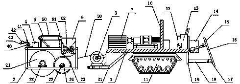
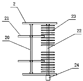
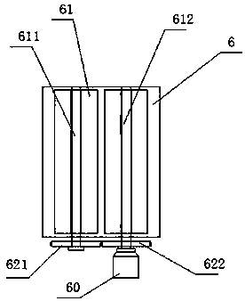
[0027] see Figure 1~6 , in the embodiment of the present invention, a traction mower for desert control includes a traction power frame 1, a grass planting frame 2, a longitudinal winch 3, a water drying device 4, a conveyor belt 5 and a grass box 6, and the traction power machine The left end of the frame 1 is fixedly provided with a longitudinal hoist frame 31, the longitudinal hoist 3 is fixedly arranged on the longitudinal hoist frame 1, the...


PUM


Abstract

The invention discloses a traction grass planter for desert control. The traction grass planter comprises a traction power rack, a grass planting rack, a longitudinal hoisting machine, a water spraying device, a conveyor belt and a grass box; a longitudinal hoisting machine rack is fixedly arranged at the left end of the traction power rack, the longitudinal hoisting machine is fixedly disposed onthe longitudinal hoisting machine rack, an output end of the longitudinal hoisting machine is connected with a steel wire rope, and the other end of the steel wire rope is fixedly disposed on the grass planting rack; a machine frame of the grass planting rack is sequentially provided with the water spraying device, a conveying device and the grass box from left to right. Through a walking caterpillar band, the traction power rack walks more stably in a desert, so that the overall efficiency of the grass planter is improved. Through arrangement of the water spraying device, water is sprayed onto grass seeds or tree seeds in grass squares synchronously, so that the survival rate of the grass seeds or tree seeds is increased. Through mechanized equipment, the overall grass planting efficiency is improved, and the work intensity of operators is reduced.

Description

technical field [0001] The invention relates to the technical field of desert control, in particular to a traction grass planter for desert control. Background technique [0002] At present, the land desertification in the country is becoming more and more serious. People adopt various methods to fix and control sand. The most obvious method is to realize large-scale afforestation in desert areas. However, due to the harsh environment in desert areas, no matter whether it is trees or grass The survival rate of large sandstorms is very low. In the process of desert control, the first thing is to seal the sand. The sand seal is to fix the sand in place and not be blown away by the wind. It creates conditions for planting plants in the future. This is the most important thing in sand control. process. Grass grid is a method of sand fixation. It is to insert grass into the sand and expose it to a certain height, form a grass grid on the surface of the sand, and use the exposed ...

Claims


Application Information

Patent Timeline
Patent Type & Authority Applications(China)
IPC IPC(8): A01B49/04A01G25/09
Inventor 佘书强
Owner 佘书强
Learn More