
Visual servo trajectory tracking and concurrent depth identification on the wheeled mobile robot

A mobile robot and trajectory tracking technology, applied in the direction of instruments, image data processing, two-dimensional position/channel control, etc., can solve the lack of depth information, the inability to obtain the scene model, and the difficulty of recovering external three-dimensional scene information and mobile robot motion information And other issues

Pending Publication Date: 2019-05-28
TIANJIN POLYTECHNIC UNIV
View PDF5 Cites 14 Cited by
  • Summary
  • Abstract
  • Description
  • Claims
  • Application Information

AI Technical Summary

Problems solved by technology

For the visual sensor, because it is based on the perspective projection model, the lack of depth information is the main defect. Therefore, for the monocular camera vision system, it is difficult to completely restore the external 3D scene information and the mobile robot's own motion information; in addition, due to the mobile robot The characteristics of nonholonomic motion constraints make the design of pose controller very challenging. Therefore, the lack of depth information and the limitation of nonholonomic constraints make the task of visual control of mobile robots extremely difficult; however, most of the existing methods Design a compensation module for unknown scene information based on the original visual servo controller
In this sense, the scene model cannot be obtained after the visual servo task is completed, and the further application and promotion of the robot system is limited because the workspace information cannot be fully obtained.

Method used


Image

  • Visual servo trajectory tracking and concurrent depth identification on the wheeled mobile robot
  • Visual servo trajectory tracking and concurrent depth identification on the wheeled mobile robot
  • Visual servo trajectory tracking and concurrent depth identification on the wheeled mobile robot

Examples


Embodiment 1

[0063] 1. A wheeled mobile robot simultaneous visual trajectory tracking concurrent adaptive depth identification method, characterized in that it comprises the following steps:

[0064] First, define the system coordinate system, including:

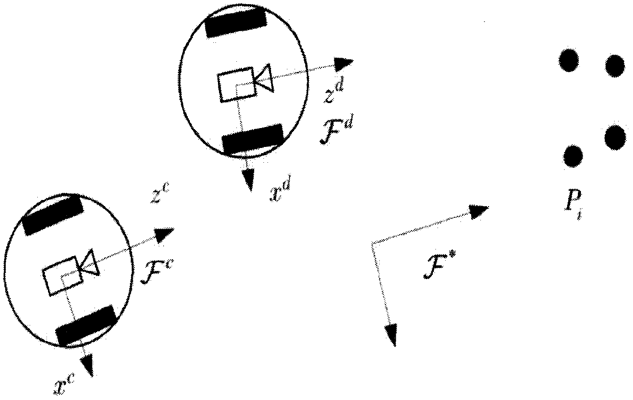
[0065] Define the coordinate system of the wheeled mobile robot as follows: Represents the reference coordinate system of the camera relative to the stationary feature point, with Indicates the current pose coordinate system of the wheeled mobile robot, with Represents the Cartesian coordinate system corresponding to the expected pose of the wheeled mobile robot, with the coplanar feature point P i The determined plane is the reference plane π, and the unit normal vector defining the plane π is n * , 3-D Euclidean coordinates P i exist Next use respectively To represent:

[0066]

[0067] Assuming that the distance from the origin of each coordinate system to the feature point along the optical axis is always positive, fro...


PUM


Abstract

The invention discloses a visual servo trajectory tracking concurrent depth identification method for a wheeled mobile robot. The visual tracking control method is designed for the wheeled mobile robot under incomplete motion constraints, and depth information of a scene can be identified while servo trajectory tracking is performed. First, an image video is recorded for coplanar feature points torepresent a desired trajectory to be tracked. Secondly, establishing a homography matrix under an Euclidean coordinate system by comparing the feature points in the static reference image, the feature points in the real-time image and a pre-recorded image video in combination with a projection geometrical relationship; Then, through a homography matrix obtained through decomposition, a motion control law and an adaptive updating law about unknown depth parameters are designed; A concurrent learning algorithm is added into an adaptive updating rate, and unknown depth information is recovered by utilizing historical and current system data. Finally, simultaneous convergence of a trajectory tracking error and a depth identification error is proved through a Lyapunov method and an extended Barra theorem, so that the method can effectively identify scene depth information.

Description

technical field [0001] The invention belongs to the technical field of computer vision and mobile robots, and in particular relates to a simultaneous visual servo trajectory tracking and adaptive depth identification method for a mobile robot, which can track a desired time-varying trajectory and identify its scene depth information. Background technique [0002] Wheeled mobile robots often work in dangerous environments. Due to the uncertain factors in the working environment, many researchers have developed various solutions to improve the autonomous control ability of the system. Recently, due to the improvement of image processing technology and the development of control algorithm theory, many researchers have adopted autonomous control technology based on visual sensors to realize autonomous navigation and control of the system. [0003] For mobile robot systems, the introduction of visual sensors can greatly enhance its intelligence, flexibility and environmental perc...

Claims


Application Information

Patent Timeline
Patent Type & Authority Applications(China)
IPC IPC(8): G06T7/246G06T7/579G05D1/02
Inventor 李宝全邱雨师五喜徐壮
Owner TIANJIN POLYTECHNIC UNIV
Learn More