A valveless piezoelectric pump with multiple bluff bodies in the cavity

A valveless piezoelectric pump and bluff body technology, which is applied to parts of pumping devices for elastic fluids, pumps with flexible working elements, pumps, etc., can solve the problems of low output flow and serious backflow, and achieve improved Output flow, the effect of relieving backflow

Active Publication Date: 2020-05-12
CHANGCHUN UNIV OF TECH
View PDF10 Cites 0 Cited by
  • Summary
  • Abstract
  • Description
  • Claims
  • Application Information

AI Technical Summary

Problems solved by technology

[0002] Applying the inverse piezoelectric effect of the single-chip piezoelectric vibrator to the valveless piezoelectric pump can realize the circulation output of the liquid. Due to the advantages of small size and no electromagnetic interference, the valveless piezoelectric pump has attracted people's attention in recent years. However, valveless piezoelectric pumps also have the disadvantages of serious backflow and low output flow, which makes it difficult for valveless piezoelectric pumps to be widely used in daily life.

Method used


Image

  • A valveless piezoelectric pump with multiple bluff bodies in the cavity
  • A valveless piezoelectric pump with multiple bluff bodies in the cavity
  • A valveless piezoelectric pump with multiple bluff bodies in the cavity

Examples


Embodiment Construction

[0018] In order to enable those skilled in the art to better understand the technical solution of the present invention, the present invention will be described in detail below in conjunction with the accompanying drawings. The description in this part is only exemplary and explanatory, and should not have any limiting effect on the protection scope of the present invention. .

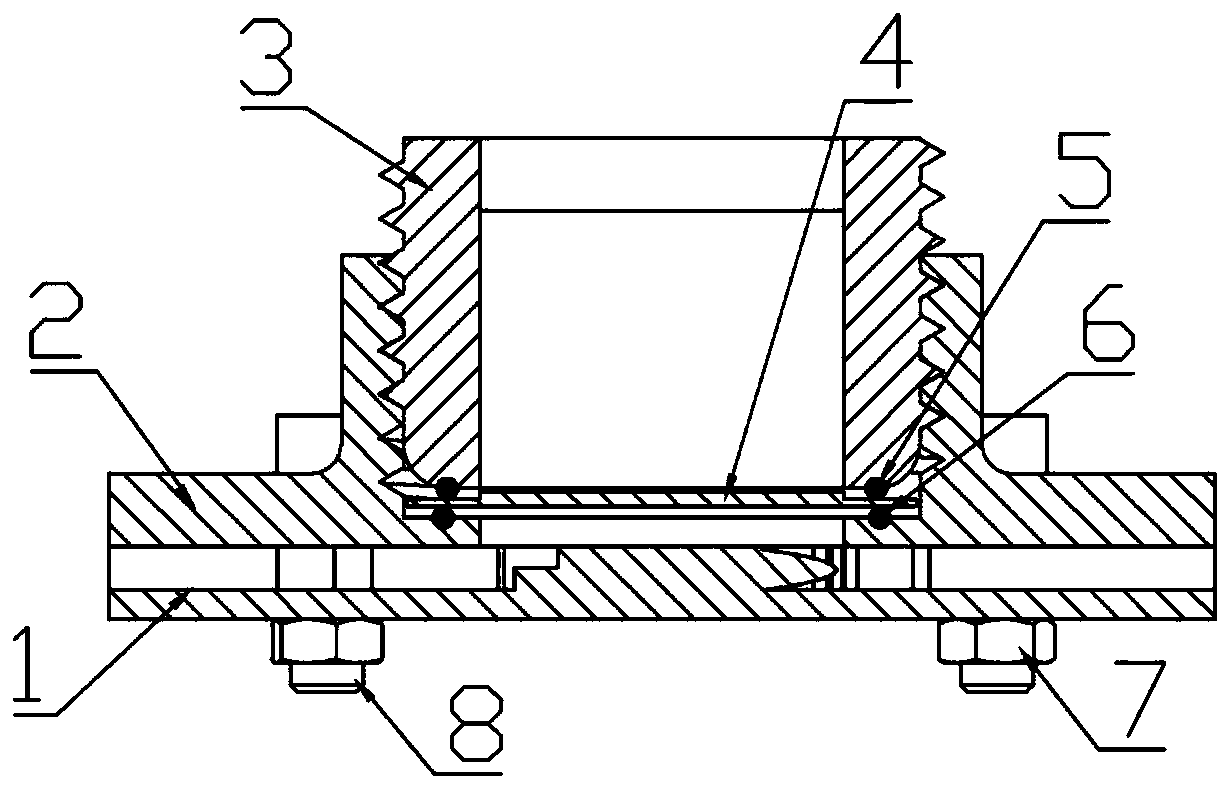
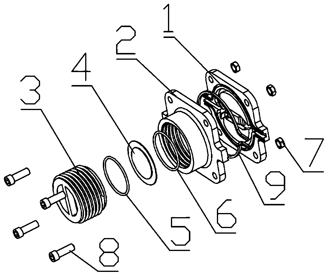
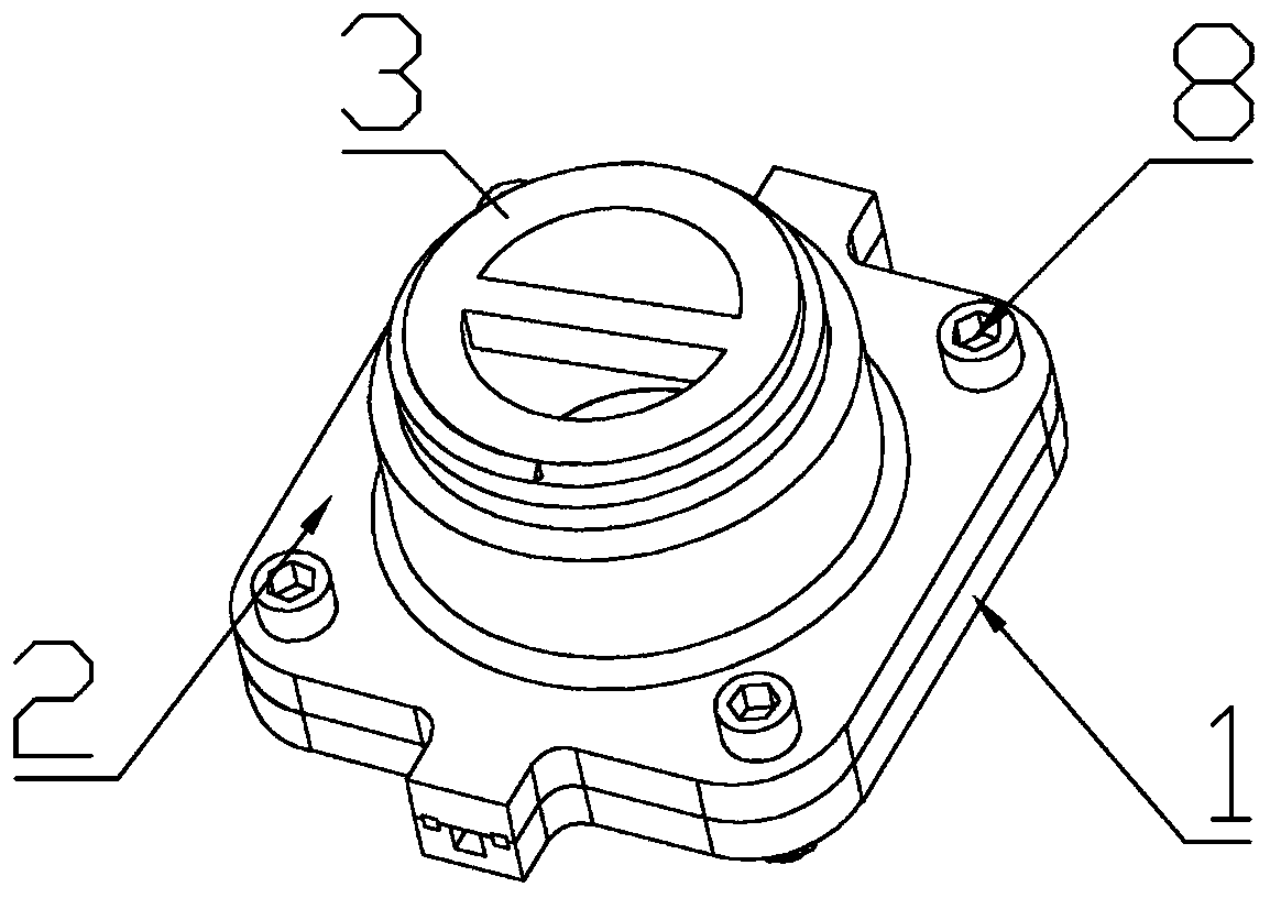
[0019] see Figure 1-6 , in the embodiment of the present invention, the specific structure includes:

[0020] A valveless piezoelectric pump with multiple bluff bodies in the cavity, which consists of a lower pump body (1), an upper pump body (2), a screw upper cover (3), a single-chip piezoelectric vibrator (4), and a sealing ring (5 ), a rubber ring (6), a fastening nut (7), a fastening screw (8) and an annular sealing ring (9); the lower pump body (1) has a liquid inlet (1-1) and a liquid outlet port (1-2), the lower pump body (1) is provided with an outer flow channel (1-4), and the outer flow c...


PUM


Abstract

The invention discloses a valve-free piezoelectric pump of a plurality of fluids inside a cavity. The valve-free piezoelectric pump comprises a lower pump body, an upper pump body, a spiral upper cover, a single-crystal piezoelectric vibrator, a sealing ring, a rubber ring, a fastening screw, a fastening nut and an annular sealing ring. An outer flow channel is formed inside the lower pump body. Aflow baffle is arranged on the inner side of the outer flow channel. A diversion arc structure is arranged on the side, close to a liquid inlet, of the flow baffle. A round top flow blocking body, atrapezoidal flow blocking body and a stepped flow blocking body are arranged in the pump cavity. An upper sealing groove formed in the upper pump body is matched with a lower sealing groove formed inthe lower pump body. An annular sealing ring is arranged between the upper sealing groove and the lower sealing groove. A threaded groove is formed in the upper pump body. A sealing ring sealing groove is formed below the spiral upper cover. The single-crystal piezoelectric vibrator is fixed through the matching of right-handed threads and a threaded groove of the upper pump body, and a fasteningscrew is matched with a fastening nut to assemble the upper pump body and the lower pump body so as to complete the assembly of the pump.

Description

technical field [0001] The invention relates to a valveless piezoelectric pump with multiple blocking bodies in a cavity, which belongs to the field of fluid machinery. Background technique [0002] Applying the inverse piezoelectric effect of the single-chip piezoelectric vibrator to the valveless piezoelectric pump can realize the circulation output of the liquid. Due to the advantages of small size and no electromagnetic interference, the valveless piezoelectric pump has attracted people's attention in recent years. However, valveless piezoelectric pumps also have the disadvantages of serious backflow and low output flow, which makes it difficult for valveless piezoelectric pumps to be widely used in daily life. Contents of the invention [0003] Aiming at the problems existing in the current valveless piezoelectric pump, the present invention proposes a valveless piezoelectric pump capable of alleviating backflow and having high output flow. [0004] The technical sol...

Claims


Application Information

Patent Timeline
Patent Type & Authority Patents(China)
IPC IPC(8): F04B43/04F04B53/00
Inventor 何丽鹏吴晓强程廷海李威杨丽梅
Owner CHANGCHUN UNIV OF TECH
Why Eureka
Try Eureka