Cast-in-situ bridge formwork support system device and bridge cast-in-situ construction method

A cast-in-place bridge and formwork technology, applied in bridges, bridge construction, erection/assembly of bridges, etc., can solve problems such as the inability to meet the needs of rapid construction of bridge concrete, avoid tedious processes and material turnover space and costs, and shorten the construction period. , The effect of reducing the waste of construction period

Pending Publication Date: 2019-05-24
CHINA RAILWAY NO 9 GRP 2ND ENG +1
View PDF0 Cites 1 Cited by
  • Summary
  • Abstract
  • Description
  • Claims
  • Application Information

AI Technical Summary

Problems solved by technology

[0004] The technical problem to be solved by the present invention is to provide a cast-in-place bridge formwork support system device and a bridge cast-in-place construction method to solve the technical problem that the traditional cast-in-place large-volume concrete support construction cannot meet the current rapid construction requirements of bridge concrete

Method used


Image

  • Cast-in-situ bridge formwork support system device and bridge cast-in-situ construction method
  • Cast-in-situ bridge formwork support system device and bridge cast-in-situ construction method
  • Cast-in-situ bridge formwork support system device and bridge cast-in-situ construction method

Examples


Embodiment Construction

[0034] In the following description, for purposes of explanation, numerous specific details are set forth in order to provide a thorough understanding of one or more embodiments. It may be evident, however, that these embodiments may be practiced without these specific details. In other instances, well-known structures and devices are shown in block diagram form in order to facilitate describing one or more embodiments.

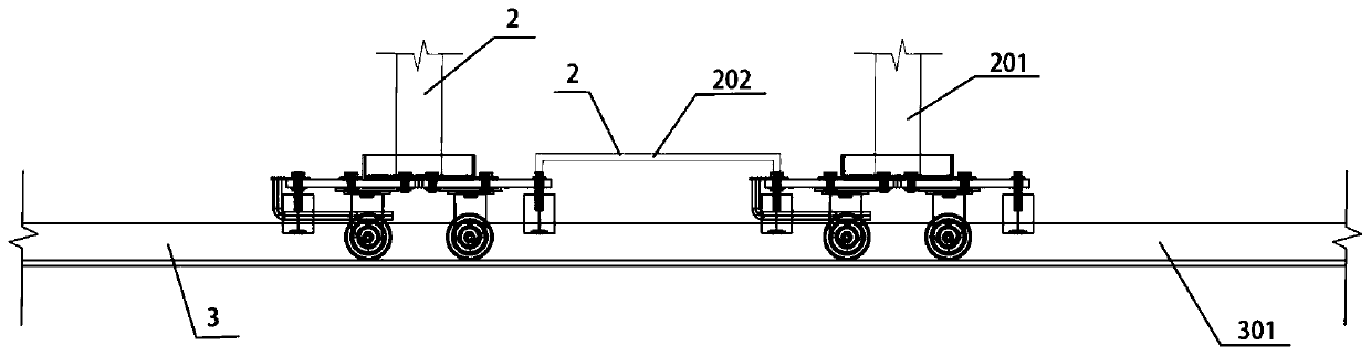
[0035] figure 1 The front view structure of the cast-in-place bridge formwork support system device provided by the embodiment of the present invention is shown.

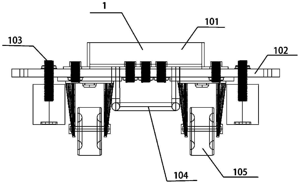
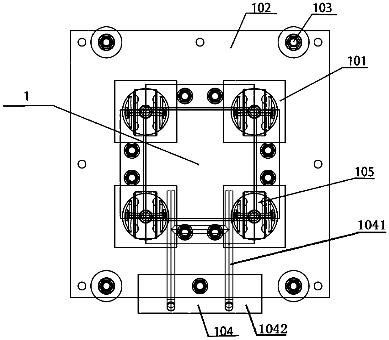
[0036] Such as figure 1 As shown, the cast-in-place bridge formwork support system device provided by the present invention includes: a sliding mechanism 1, a scaffolding connection structure 2 and a grooved track structure 3, and there are at least two sets of sliding mechanisms 1, respectively in the grooved track structure 3 moves along the groove track structure 3, and the two adjacent sets ...


PUM


Abstract

The invention provides a cast-in-situ bridge formwork support system device and a bridge cast-in-situ construction method. The device comprises at least two slip mechanisms, all-round scaffold connecting structures and groove track structures, the slip mechanisms move on the groove track structures, two adjacent slip mechanisms are connected through the all-round scaffold connecting structures, and all-round scaffolds are fixed onto the slip mechanisms and driven by the slip mechanisms to move along the groove track structures. By the aid of manpower or tools such as a hoister, the all-round scaffolds are rapidly and integrally migrated to a next construction section or specific position, slip directions can be adjusted at any time in the process, and the cumbersome procedures of assembling and disassembling supports are omitted. Compared with a traditional bridge construction method, the method is more convenient in construction, construction period is saved, labor input can be reduced, the cumbersome procedures of repeatedly disassembling the supports are omitted, and material turnover space and cost are reduced.

Description

technical field [0001] The invention belongs to the technical field of scaffolding sliding, and in particular relates to a cast-in-place bridge formwork support system device and a bridge cast-in-place construction method. Background technique [0002] With the rapid development of the construction of railway passenger dedicated lines, new passenger dedicated lines have become a prerequisite for national economic development. Therefore, there are a large number of line and bridge constructions for new passenger dedicated lines. The construction of bridges, especially the construction of cast-in-place beams, is faced with the heavy traffic pressure of the existing roads, the safety of vehicles and pedestrians, and the limitations of scarce work space. This puts forward higher requirements for the design of cast-in-place beam brackets and formwork systems for cable renovation—not only to meet the requirements of economy, safety, and convenience of assembly, disassembly and tr...

Claims


Application Information

Patent Timeline
Patent Type & Authority Applications(China)
IPC IPC(8): E01D21/00
Inventor 徐世文杨永伟刘秉辉于成波赵大军郭金龙谷金鑫娄英奎郭瀚书姚富智田野刘哲明袁绍立
Owner CHINA RAILWAY NO 9 GRP 2ND ENG
Why Eureka
Try Eureka