
Medical device and fixing mechanism of medical equipment

A technology of medical equipment and fixation mechanism, applied in the directions of therapy, electrotherapy, cardiac stimulator, etc., can solve the problem that leadless pacemaker cannot fix the atrium, atrioventricular desynchronization and non-physiological pacing, and cannot realize dual-chamber pacing. and other problems to achieve the effect of improving medical effects, preventing tissue damage, and reducing length

Inactive Publication Date: 2019-05-24
MICROPORT SORIN CRM (SHANGHAI) CO LTD
View PDF6 Cites 5 Cited by
  • Summary
  • Abstract
  • Description
  • Claims
  • Application Information

AI Technical Summary

Problems solved by technology

However, due to the thin wall of the atrium, if the helical structure leadless pacemaker is fixed in the thin-walled atrium, there will be major risks such as loose fixation and atrial perforation.
That is, the existing leadless pacemaker cannot be fixed in the atrium
[0005] Therefore, the current leadless pacemaker can only be fixed at the apex of the right ventricle, so that the current leadless pacemaker can only achieve ventricular single-chamber pacing, and cannot achieve dual-chamber pacing (DDD pacing mode). Therefore, The existing leadless pacemakers easily lead to non-physiological pacing of atrioventricular desynchronization, so that the population that can really benefit from leadless pacing technology is relatively limited, and it is generally only used for chronic atrial fibrillation and elderly patients

Method used


Image

  • Medical device and fixing mechanism of medical equipment
  • Medical device and fixing mechanism of medical equipment
  • Medical device and fixing mechanism of medical equipment

Examples


Embodiment Construction

[0057] In order to make the purpose, advantages and features of the present invention clearer, the present invention will be further described in detail below in conjunction with the accompanying drawings. It should be noted that all the drawings are in a very simplified form and use imprecise scales, and are only used to facilitate and clearly assist the purpose of illustrating the embodiments of the present invention.

[0058] As used herein, the terms "cranial", "caudal" and "proximal", "distal" refer to the relative orientation, relative position, direction, , although "head end", "tail end" and "proximal end" and "distal end" are not limiting, but "tail end" and "proximal end" generally refer to the One end, while "head end" and "distal end" usually refer to the end that first enters the patient's body.

[0059] As used in this specification and the appended claims, the singular forms "a," "an," and "the" include plural referents unless the content clearly dictates other...


PUM


Abstract

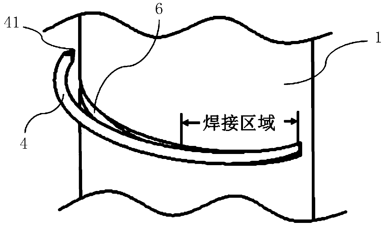
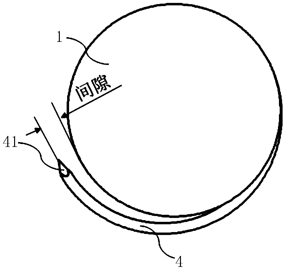
The invention provides a medical device and a fixing mechanism of medical equipment. The medical equipment can be conveniently located at a target position in the body through the fixing mechanism toachieve corresponding implantation or interventional treatment of the medical equipment, and accordingly, the medical effect is improved. The medical equipment can be a lead-free pacemaker, and physiological pace-making on the heart by the pacemaker is conveniently realized. The fixing mechanism comprises a base and fixing member, the extension direction of the base is parallel to that of a presetobject, and the fixing member is arranged on the outer wall of the base and extends around the base; one end of the fixing member is connected with the outer wall of the base, and a gap is formed between the other end of the fixing member and the outer wall of the base. During actual use, the base is stressed to rotate along the extension direction of the fixing member, and drives the fixing member to rotate together; during rotation, the fixing member is directly inserted into a tissue or a blood vessel wall parallel to the base, so that the medical equipment can be fixed into the atrium, the ventricle, the precava or other blood vessels, or fixed onto the interventricular septum or the interatrial septum.

Description

technical field [0001] The invention relates to the technical field of medical devices, in particular to a medical device and a fixing mechanism for the medical device. Background technique [0002] Since its introduction in 1958, cardiac pacemakers have become the first-line treatment for bradyarrhythmia diseases. After more than half a century of development and innovation, the cardiac pacemaker has gradually developed from implanting a single electrode lead through the chest to pace the ventricle to providing 2 to 3 electrode leads transvenously to provide atrioventricular physiological pacing and even Synchronized biventricular pacing. However, lead dislocation, thrombosis, tricuspid regurgitation, infection and lead-related complications have not only affected the normal use of pacemakers, but also seriously endangered the life, health and quality of life of patients. Among them, when the infection is related to the complications of the lead, the lead should be remove...

Claims


Application Information

Patent Timeline
Patent Type & Authority Applications(China)
IPC IPC(8): A61N1/375
CPCA61N1/362A61N1/37518A61N1/3756A61N1/0573A61N1/37512A61N1/37516
Inventor 王励程志军
Owner MICROPORT SORIN CRM (SHANGHAI) CO LTD
Learn More