
Radio frequency coil tuning methods and apparatus

A technology of radio frequency coils and tuning components, applied in continuous tuning parts, multiple resonant circuits tuned to the same frequency, the size/direction of the magnetic field, etc., can solve the problems of high cost of equipment, limited availability of clinical MRI scanners, etc.

Active Publication Date: 2019-05-21
HYPERFINE
View PDF8 Cites 3 Cited by
  • Summary
  • Abstract
  • Description
  • Claims
  • Application Information

AI Technical Summary

Problems solved by technology

However, MRI suffers from several disadvantages that may involve, for a given imaging application, the relatively high cost of the equipment, limited availability and / or difficulty in obtaining access to clinical MRI scanners, and / or the image acquisition process length
The high cost and substantial space requirements of high-field MRI systems lead to limited availability of MRI scanners

Method used


Image

  • Radio frequency coil tuning methods and apparatus
  • Radio frequency coil tuning methods and apparatus
  • Radio frequency coil tuning methods and apparatus

Examples


Embodiment Construction

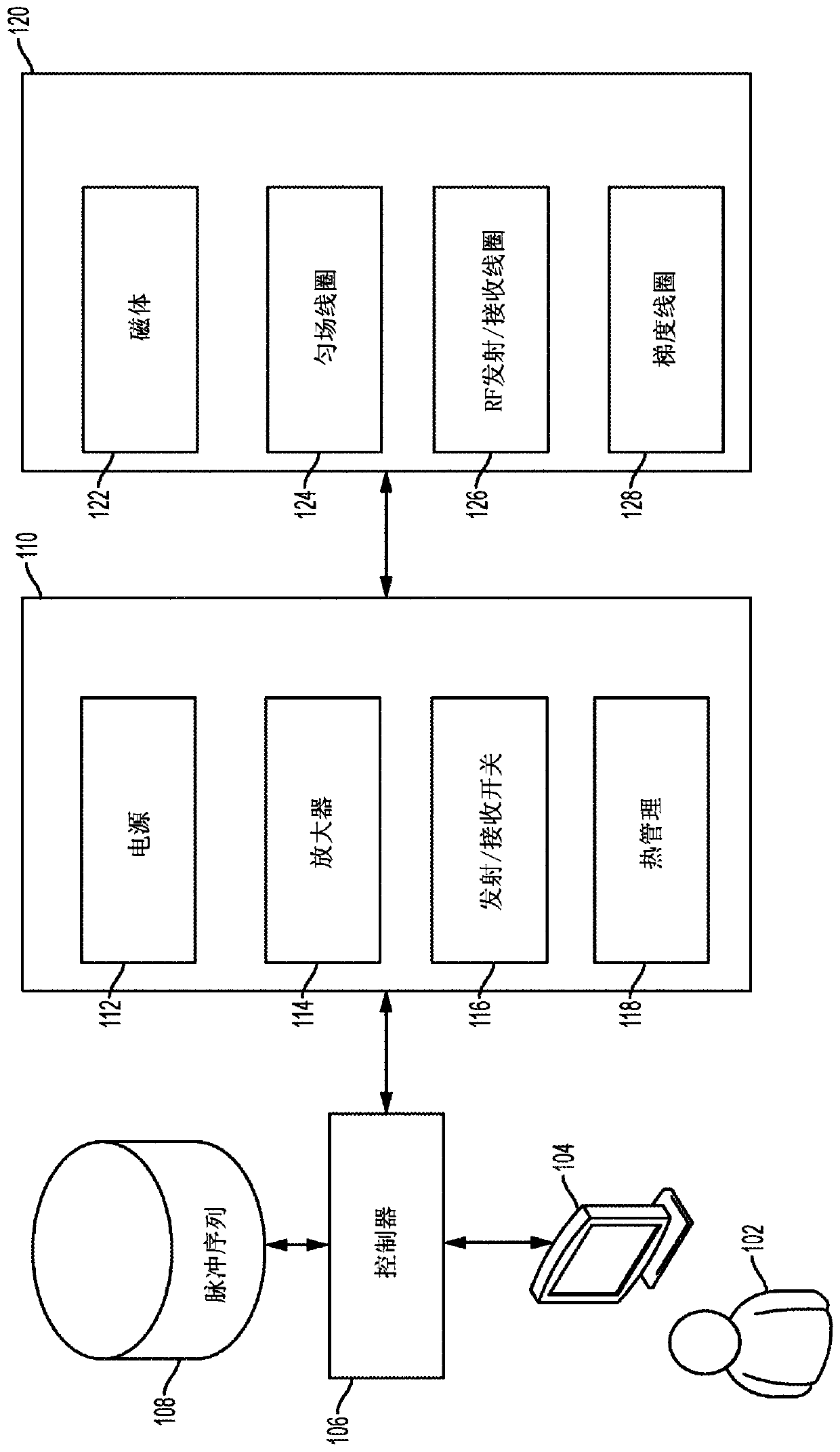
[0026] The MRI scanner market is overwhelmingly dominated by high-field systems, especially for medical or clinical MRI applications. As discussed above, the general trend of medical imaging is to produce MRI scanners with increasingly larger field strengths. Among them, the vast majority of clinical MRI scanners work at 1.5T or 3T, and use 7T and 9T in research environments. The higher field strength. As used herein, "high field" generally refers to MRI systems currently used in clinical environments, and more specifically, it refers to the use of a main magnetic field of 1.5T or above (ie B 0 Field) operating MRI systems, although clinical systems operating between 0.5T and 1.5T are often described as "high field". The field strength between about 0.2T and 0.5T has been described as "midfield", and as the field strength in the high field continues to increase, the field strength in the range between 0.5T and 1T has also been described as Midfield. In contrast, "low field" u...


PUM


Abstract

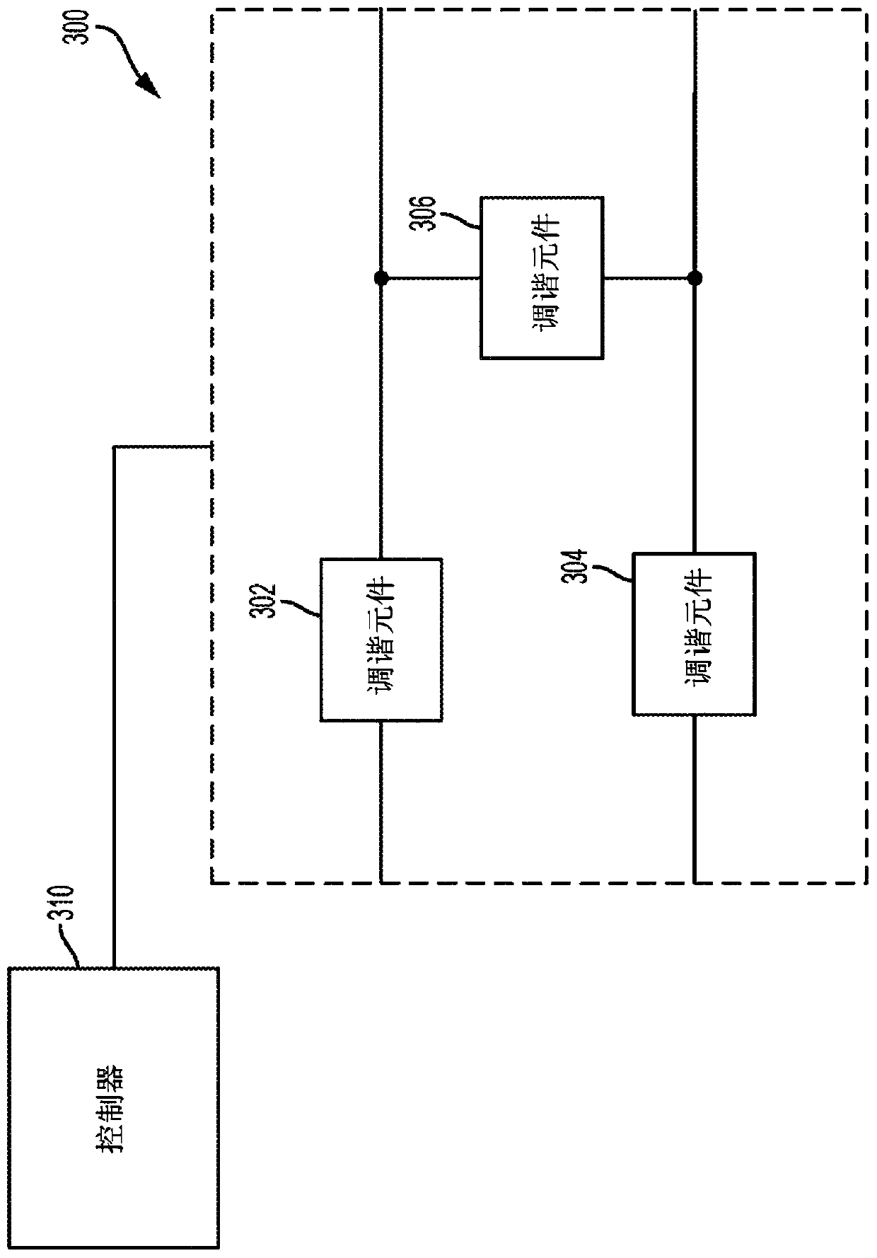
Some aspects comprise a tuning system configured to tune a radio frequency coil for use with a magnetic resonance imaging system comprising a tuning circuit including at least one tuning element configured to affect a frequency at which the radio frequency coil resonates, and a controller configured to set at least one value for the tuning element to cause the radio frequency coil to resonate at approximately a Larmor frequency of the magnetic resonance imaging system determined by the tuning system. Some aspects include a method of automatically tuning a radio frequency coil comprising determining information indicative of a Larmor frequency of the magnetic resonance imaging system, using a controller to automatically set at least one value of a tuning circuit to cause the radio frequencycoil to resonate at approximately the Larmor frequency based on the determined information.

Description

Background technique [0001] Magnetic resonance imaging (MRI) provides an important imaging mode for many applications and is widely used in clinical and research environments to produce images of the inside of the human body. Generally, MRI is based on detecting magnetic resonance (MR) signals, which are electromagnetic waves emitted by atoms in response to changes in state caused by an applied electromagnetic field. For example, nuclear magnetic resonance (NMR) technology involves the detection of MR signals emitted from the nuclei of excited atoms during the rearrangement or relaxation of nuclear spins of atoms in an imaged object (for example, atoms in human tissue). The detected MR signals can be processed to produce an image, which in the context of medical applications enables the study of internal structures and / or biological processes in the body for diagnostic, therapeutic, and / or research purposes. [0002] MRI provides an attractive imaging mode for biological imaging ...

Claims


Application Information

Patent Timeline
IPC IPC(8): G01R33/025G01R33/20G01R33/32G01R33/36G01R33/58H03J3/12H03J3/24H01F7/02
CPCG01R33/3628G01R33/445G01R33/24G01R33/583
Inventor 托德·雷亚里克杰里米·克里斯托弗·乔丹格雷戈里·L·哈尔瓦特马修·斯科特·罗森
Owner HYPERFINE
Learn More