Disturbing magnetic field compensation method

A technology of interference magnetic field and compensation method, which is applied in the direction of stray field compensation, the size/direction of magnetic field, etc., can solve the problem of occupying a large space and achieve the effect of reducing the influence of magnetic field

Active Publication Date: 2019-05-21
CSIC NO 710 RES & DEV INST
View PDF14 Cites 3 Cited by
  • Summary
  • Abstract
  • Description
  • Claims
  • Application Information

AI Technical Summary

Problems solved by technology

If the measured object and its related tooling and other auxiliary equipment occupy a large space, the distance between the compensation sensor and the center of the measured object is 1m, and the magnetic field coil constant of the compensation winding at the two positions differs by 17.6%. At this time, the theoretical best compensation effect is only It can reach 82.4% (the corresponding compensation efficiency is about 15dB), which is very different from the actual best compensation effect of more than 60dB, which does not consider the inconsistency between the working area of ​​the standard magnetic field coil and the position of the tracking compensation sensor.

Method used


Image

  • Disturbing magnetic field compensation method

Examples


Embodiment Construction

[0020] Examples are listed below to further describe the present invention in detail.

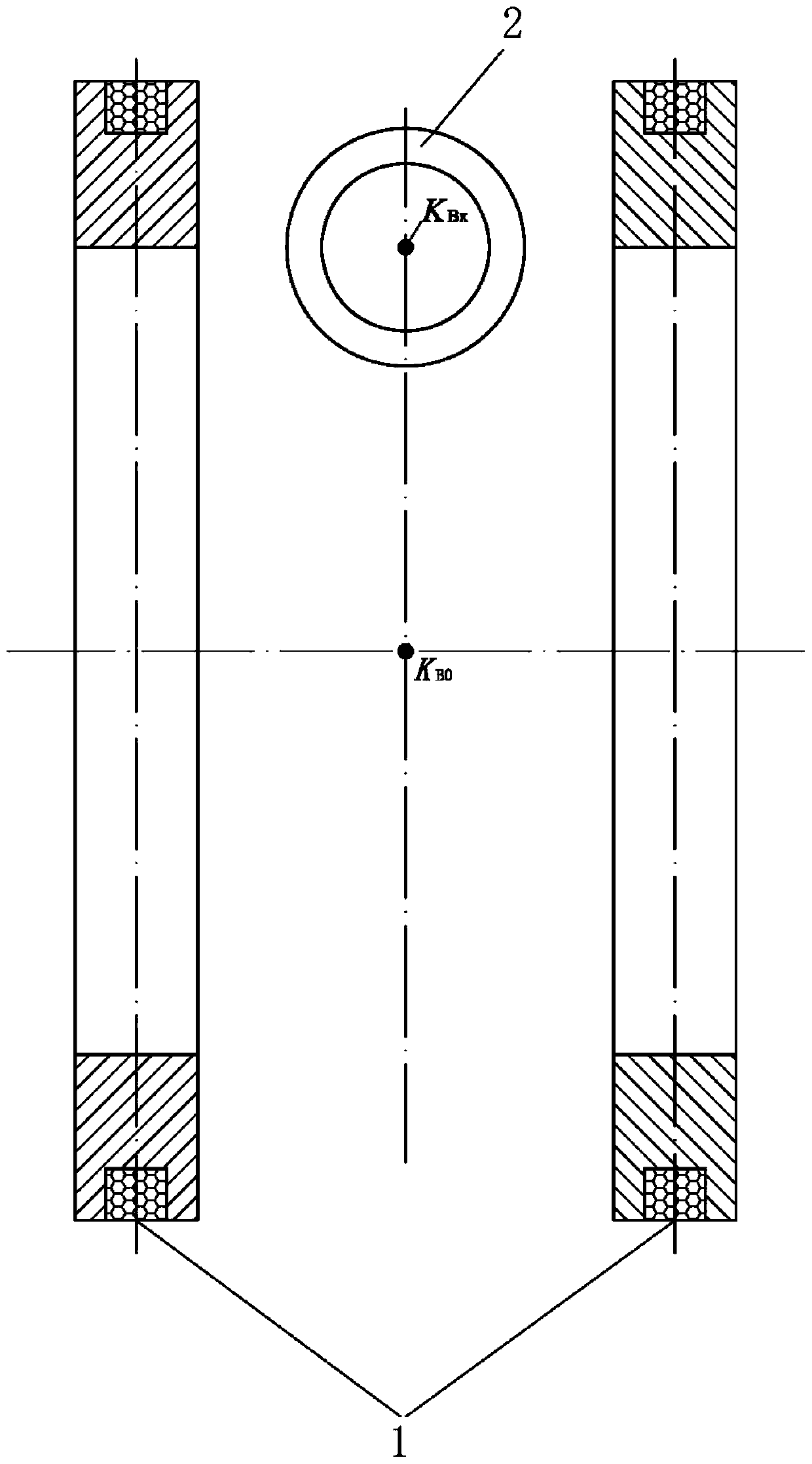
[0021] This embodiment provides this kind of interference magnetic field compensation method when the tracking compensation sensor is in the non-working area of ​​the magnetic field coil, which can eliminate the difference in the field coil constant of the primary compensation winding caused by the increase of the distance, and make the primary field coil in the standard magnetic field coil The magnetic field coil constant of the compensation winding at the position of the sensor for tracking compensation is equal to the magnetic field coil constant at the position of the measured object.

[0022] In the weak magnetic field measurement test, the standard magnetic field is generated by the magnetic field coil, and then the measured object is placed in the working area of ​​the magnetic field coil. In order to eliminate the interference magnetic field, it is necessary to design the interferenc...


PUM


Abstract

The invention provides a disturbing magnetic field compensation method. The disturbing magnetic field compensation method is specifically applied to a tracking and compensation sensor at the positionof a non-working region of a magnetic field coil and can eliminate the difference, caused by distance prolonging, between coil constants of a primary compensation winding. According to the method, onthe basis of a conventional disturbing magnetic field compensation system, a secondary compensation winding is added to the position of the tracking and compensation sensor, so that the magnetic fieldcoil constant, at the position of the tracking and compensation sensor, of the primary compensation winding in the disturbing magnetic field compensation system is equal to the magnetic field coil constant at the position of a detected sensor. The method can eliminate the difference, caused by inconsistency between the position of the compensation sensor and the position of the detected object, between the magnetic field coil constants of the primary compensation winding, so that the disturbing magnetic field compensation system achieves the optimal compensation effect.

Description

technical field [0001] The invention relates to a disturbance magnetic field compensation technology, in particular to a disturbance magnetic field compensation method when a tracking compensation sensor is in a non-working area of ​​a magnetic field coil. Background technique [0002] When performing a weak magnetic field measurement test, a standard magnetic field is generated by a standard magnetic field coil, and then the measured object is placed in the working area of ​​the standard magnetic field coil. However, the standard magnetic field will be affected by the interference magnetic field generated by various random disturbances such as geomagnetic fluctuations. In order to reduce or eliminate the influence of the interference magnetic field on the stability of the standard magnetic field in the working area of ​​the magnetic field coil, it is necessary to use the interference magnetic field compensation technology to compensate the interference magnetic field. The t...

Claims


Application Information

Patent Timeline
Patent Type & Authority Applications(China)
IPC IPC(8): G01R33/025G01R33/02
Inventor 程华富张海波周昌剑翟晶晶李享
Owner CSIC NO 710 RES & DEV INST
Why Eureka
Try Eureka