A cleaning process for network port components of network communication equipment

A network communication and network port technology is applied in the field of cleaning process of network port components of network communication equipment, which can solve the problems of chip corrosion, corrosion, poor contact of network cable access network port, etc., so as to improve the effectiveness of adsorption treatment and prevent cleaning. Dead angle, the effect of improving effectiveness

Inactive Publication Date: 2020-08-21
杭州文德风匠科技有限公司
View PDF8 Cites 0 Cited by
  • Summary
  • Abstract
  • Description
  • Claims
  • Application Information

AI Technical Summary

Problems solved by technology

[0003] When the communication network equipment in a large-scale production workshop is in operation, some network ports will be idle. Because the environment of the large-scale production workshop is dusty, and the access port of the network port is in an exposed environment, the dust accumulates in the network port, and the chip components of the network port are caused by dust. Oxidation and corrosion caused by the adhesion of the network cable, resulting in poor contact when the network cable is connected to the network port, and the network port cannot be used normally. The existing method is to regularly remove the network port and related access components for regular dust cleaning, which requires multiple times Plug and remove the access components and clean the dust. Because the chip is located inside the interface, the dead corner of dust accumulation generated by the existing dust cleaning operation will still cause corrosion to the chip and make the chip unable to work normally.

Method used


Image

  • A cleaning process for network port components of network communication equipment
  • A cleaning process for network port components of network communication equipment
  • A cleaning process for network port components of network communication equipment

Examples


Embodiment Construction

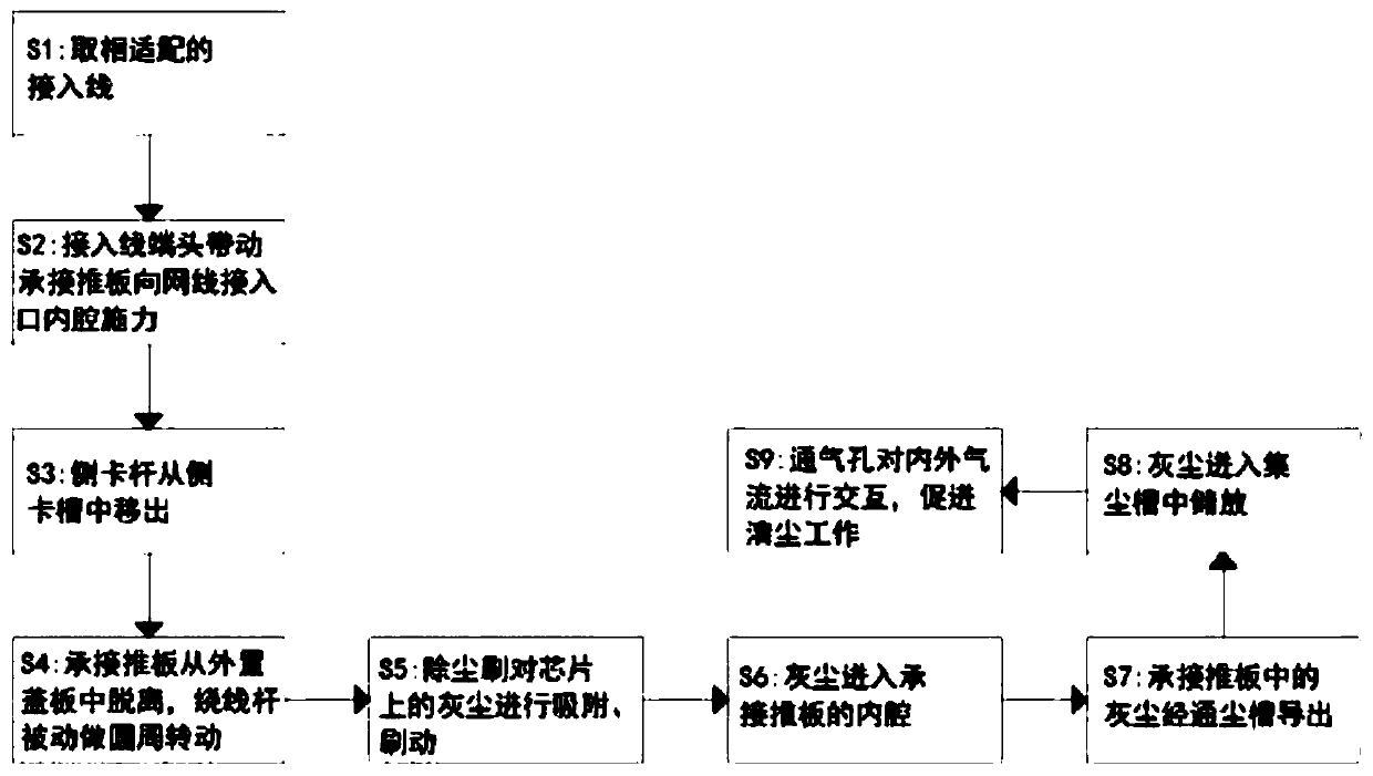
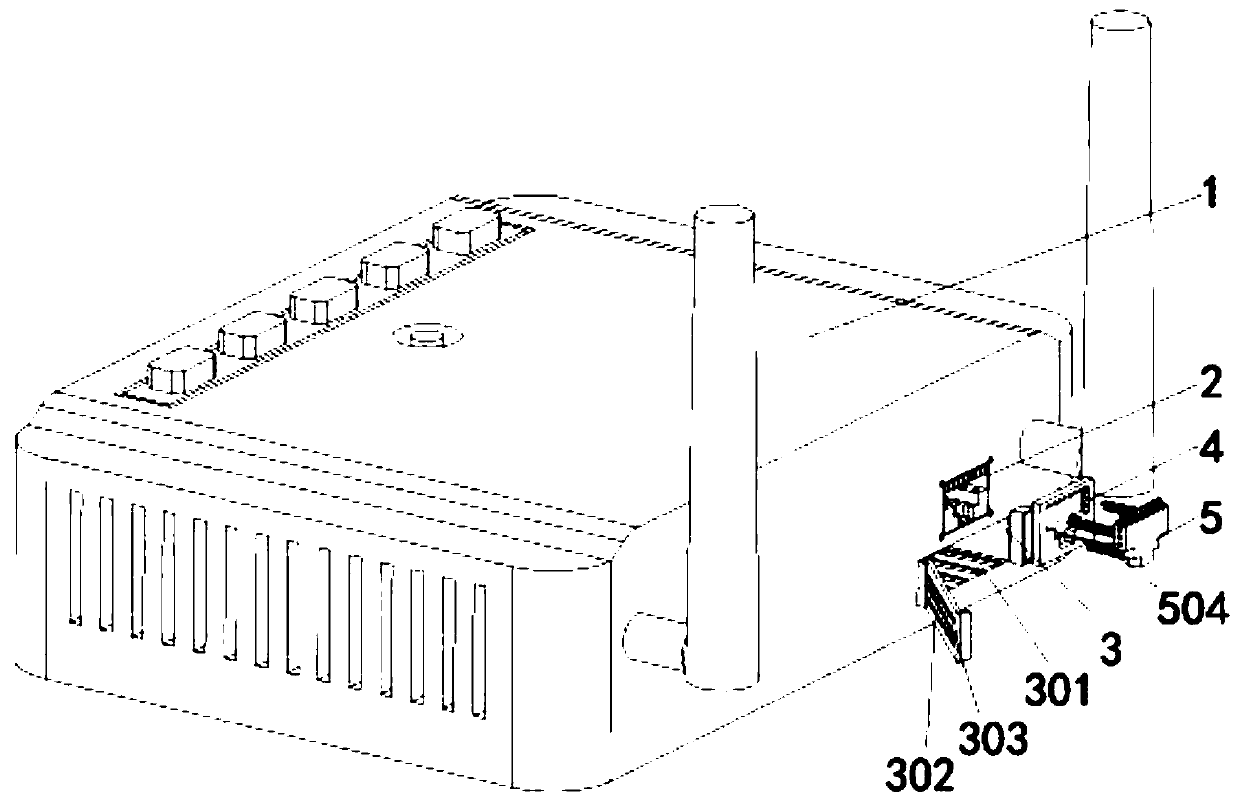
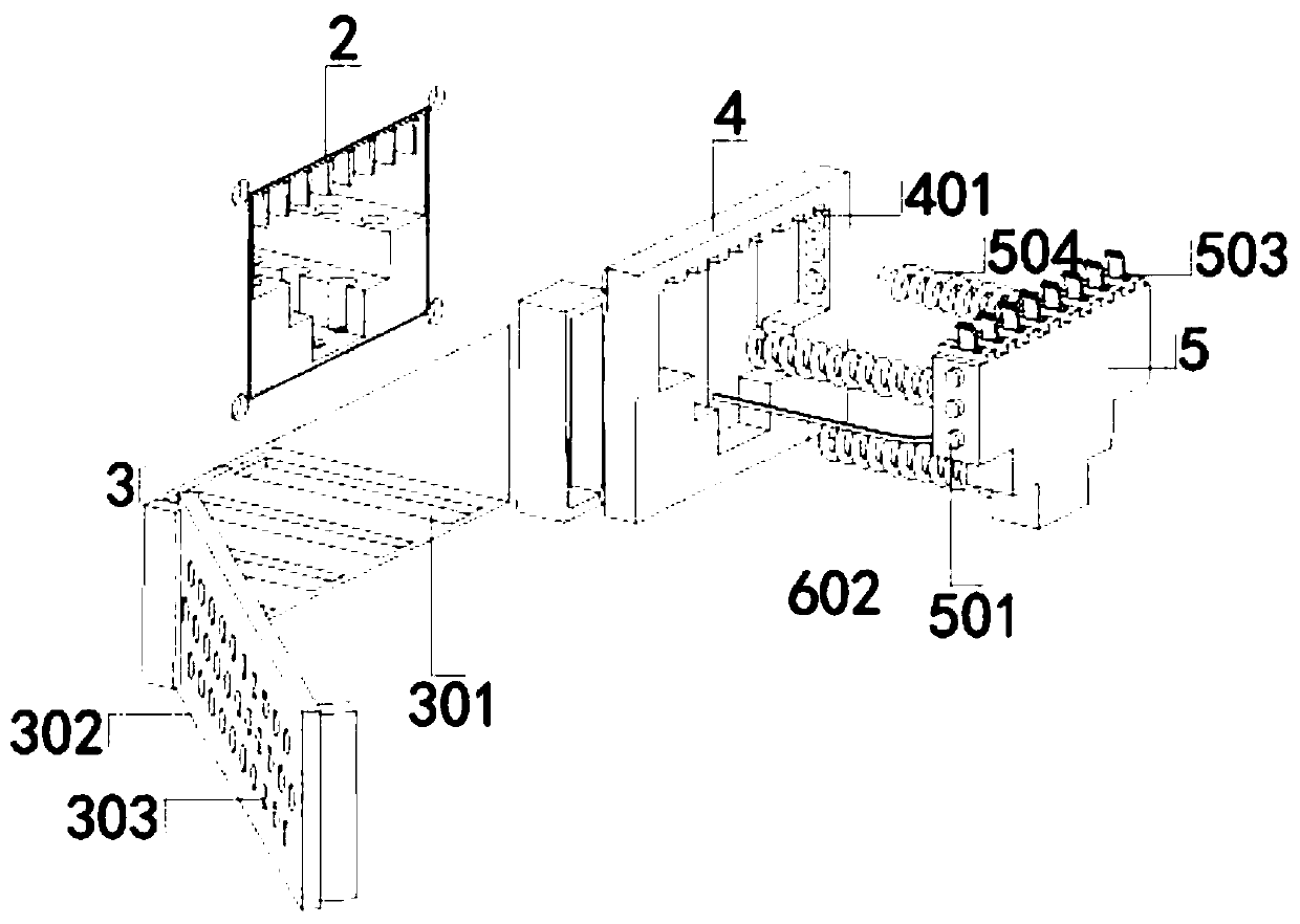
[0038] use Figure 1 to Figure 7 A dust cleaning process for network port components of network communication equipment according to the present invention is described as follows.

[0039] like Figure 1 to Figure 7 As shown, a kind of dust removal process for the network port assembly of network communication equipment of the present invention, the process includes the following steps:

[0040] S1: Take the access line that matches the network port on the front of the network communication device;

[0041] S2: Make the end of the access line in S1 stick to the front of the receiving push plate, and apply a force to the inner cavity of the network port on the receiving push plate;

[0042] S3: During the process of inserting the end of the access line into the inner cavity of the network port in S2, the side clamping rod deforms and moves out of the side clamping slot;

[0043] S4: After removing the side clamping rod of S3 from the side clamping slot, the receiving push pl...


PUM


Abstract

The invention belongs to the technical field of dust removal processes for network interface assemblies and particularly relates to a dust removal process for a network communication equipment networkport assembly. The process comprises the following steps: S1, taking an access line adapted to a network port on the positive surface of network communication equipment; and S2, enabling the end of the access line in S1 to be attached to the positive surface of a bearing push plate, and applying a force, toward an inner cavity of a net line access port, to the bearing push plate. In the process,through the combined action of an external cover plate and all components on the bearing push plate, the bearing push plate can perform adsorption, brushing and cleaning on dust on a chip in a passivestress moving process, so that operation and the steps of dust removal work on the network port assembly are simplified; and through the combined action of a dust removal brush and a moving groove, dust on the dust removal brush enters the bearing push plate through the moving groove along a spiral groove in the dust removal brush, and thus the dust removal brush has a function of timely storingthe dust while improving the effectiveness of the dust removal work on related assemblies.

Description

technical field [0001] The invention belongs to the technical field of dust removal process of network interface components, in particular to a dust removal process for network port components of network communication equipment. Background technique [0002] The traditional communication network is composed of three parts: transmission, switching and terminal. Through specific equipment, people can communicate and transmit information through the media. Communication network equipment usually has multiple network ports. At the same time, in order to increase The heat dissipation effect of the network port, the network port is usually in a semi-open state, and it also needs to be applied to communication network equipment in large-scale production workshops. [0003] When the communication network equipment in a large-scale production workshop is in operation, some network ports will be idle. Because the environment of the large-scale production workshop is dusty, and the acc...

Claims


Application Information

Patent Timeline
Patent Type & Authority Patents(China)
IPC IPC(8): B08B1/04B08B6/00B08B13/00
Inventor 不公告发明人
Owner 杭州文德风匠科技有限公司
Why Eureka
Try Eureka