
Direct drive air door mechanism

A damper, direct drive technology, applied in mechanical equipment, engine components, lift valves, etc., can solve the problems of high performance requirements, dependence, and cost increase of the reducer, and achieve the effect of flexible two-way or one-way rotation

Pending Publication Date: 2019-05-14
杨斌堂
View PDF0 Cites 3 Cited by
  • Summary
  • Abstract
  • Description
  • Claims
  • Application Information

AI Technical Summary

Problems solved by technology

[0002] In the existing technology, the rotation control mostly adopts the method of combining the motor with the reducer, but there is redundancy in the control of this method, and this method has high requirements on the performance of the reducer, and most of them rely on imported reducers, resulting in increased costs , and the volume and shape of the motor are relatively large, which is difficult to apply to application scenarios such as slender gaps

Method used


Image

  • Direct drive air door mechanism
  • Direct drive air door mechanism
  • Direct drive air door mechanism

Examples


Embodiment Construction

[0070] The present invention will be described in detail below in conjunction with specific embodiments. The following examples will help those skilled in the art to further understand the present invention, but do not limit the present invention in any form. It should be noted that those skilled in the art can make several changes and improvements without departing from the concept of the present invention. These all belong to the protection scope of the present invention.

[0071] basic embodiment

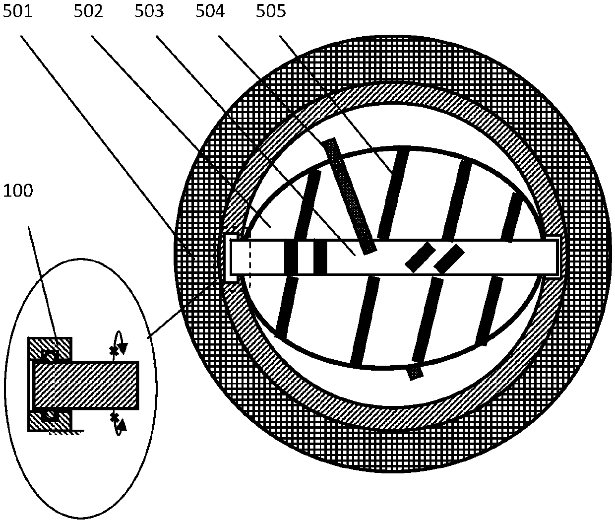
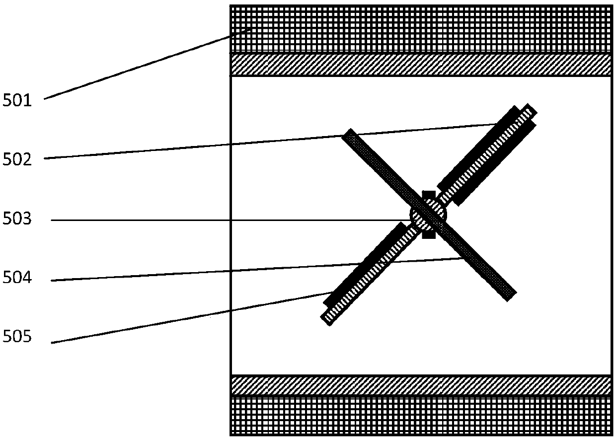
[0072] Such as figure 1 As shown, a direct drive damper mechanism provided according to the present invention includes a valve channel 501, a valve plate 502, a valve shaft 503, a first magnet member 504, a second magnet member 505, and a rotating clamping mechanism;

[0073] The valve plate 502 is installed on the valve shaft 503, and the valve plate 502 can close or open the valve channel 501 with the rotation of the valve shaft 503;

[0074] The first magnet member 504 e...


PUM


Abstract

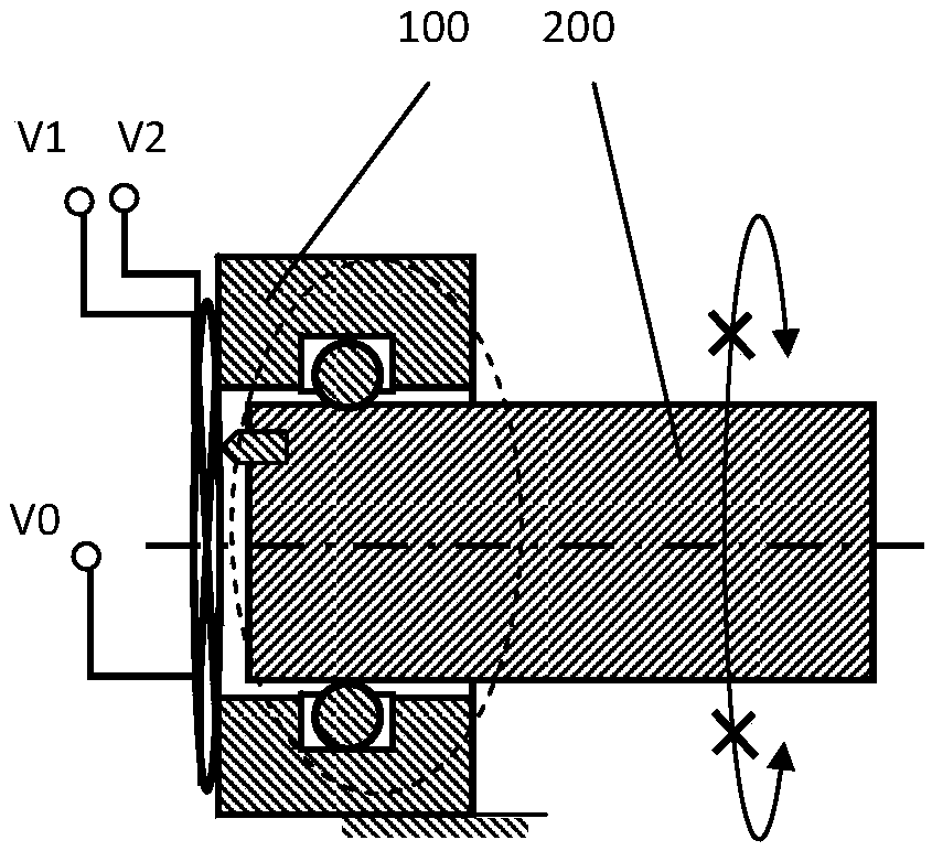
The invention provides a direct drive air door mechanism. The direct drive air door mechanism comprises a valve channel (501), a valve plate (502), a valve rotating shaft (503), a first magnetic piece(504), a second magnetic piece (505) and a rotary clamping mechanism, wherein the valve plate (502) is installed on the valve rotating shaft (503), and is capable of closing or opening the valve channel (501) as the valve rotating shaft (503) rotates; the first magnetic piece (504) extends out of the valve rotating shaft (503), and an included angle is formed between the first magnetic piece (504) and the valve plate (502); the second magnetic piece (505) is arranged on the valve rotating shaft (503) and / or the valve plate (502); and the rotary clamping mechanism is connected with the valve rotating shaft (503). The rotation angle and the opening degree of the valve rotating shaft (503) can be detected and controlled by controlling the rotation angle of a rotor (200).

Description

technical field [0001] The present invention relates to clamping mechanisms and, in particular, to direct drive damper mechanisms. Background technique [0002] In the existing technology, the rotation control mostly adopts the method of combining the motor with the reducer, but there is redundancy in the control of this method, and this method has high requirements on the performance of the reducer, and most of them rely on imported reducers, resulting in increased costs , and the volume and shape of the motor are relatively large, which is difficult to apply to application scenarios such as slender gaps. Contents of the invention [0003] Aiming at the defects in the prior art, the object of the present invention is to provide a direct-drive damper mechanism. [0004] A direct drive damper mechanism provided according to the present invention includes a valve channel 501, a valve plate 502, a valve shaft 503, a first magnet part 504, a second magnet part 505, and a rota...

Claims


Application Information

Patent Timeline
IPC IPC(8): F16K1/22F16K1/36F16K31/06
Inventor 杨斌堂
Owner 杨斌堂
Learn More