
Rotary clamping mechanism

A clamping and rotating body technology, applied in the field of rotating clamping mechanism, can solve the problems of large size and shape of the motor, increase in cost, dependence, etc., and achieve the effect of flexible bidirectional or unidirectional rotation control

Pending Publication Date: 2019-05-14
杨斌堂
View PDF0 Cites 1 Cited by
  • Summary
  • Abstract
  • Description
  • Claims
  • Application Information

AI Technical Summary

Problems solved by technology

[0002] In the existing technology, the rotation control mostly adopts the method of combining the motor with the reducer, but there is redundancy in the control of this method, and this method has high requirements on the performance of the reducer, and most of them rely on imported reducers, resulting in increased costs , and the volume and shape of the motor are relatively large, which is difficult to apply to application scenarios such as slender gaps

Method used


Image

  • Rotary clamping mechanism
  • Rotary clamping mechanism
  • Rotary clamping mechanism

Examples


Embodiment Construction

[0049] The present invention will be described in detail below in conjunction with specific embodiments. The following examples will help those skilled in the art to further understand the present invention, but do not limit the present invention in any form. It should be noted that those skilled in the art can make several changes and improvements without departing from the concept of the present invention. These all belong to the protection scope of the present invention.

[0050] basic embodiment

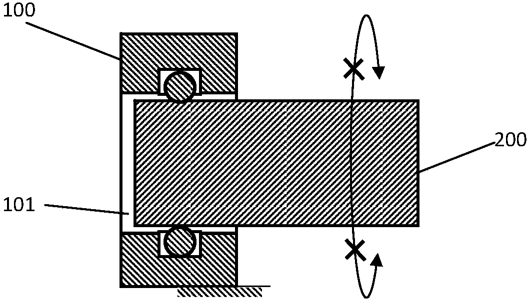
[0051] like figure 1 Shown is a basic embodiment.

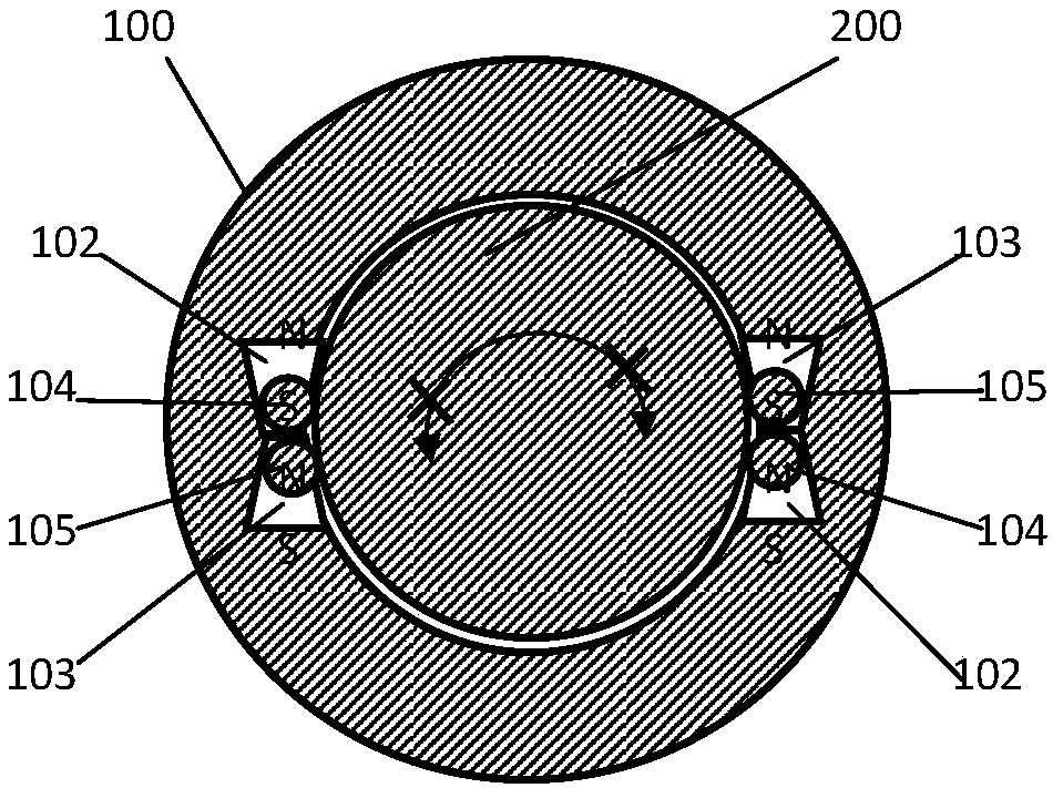
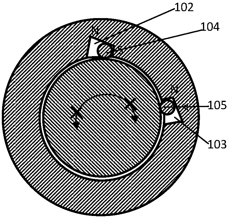
[0052]A rotation clamping mechanism provided according to the present invention includes a rotation controllable stopper 100 and a rotation body 200;

[0053] The rotation controllable stopper 100 has a rotation body receiving hole 101;

[0054] The rotating body 200 is inserted into the rotating body receiving hole 101;

[0055] In the circumferential rotation direction of the rotating body 200 , the rotation controllab...


PUM


Abstract

The invention provides a rotary clamping mechanism. The rotary clamping mechanism comprises a rotary controllable stop dog (100) and a rotator (200); the rotary controllable stop dog (100) is providedwith a rotator containing hole (101); the rotator (200) is inserted into the rotator containing hole (101); and the rotary controllable stop dog (100) can lock or release the rotator (200) in the circumferential rotary direction of the rotator (200). The rotary controllable stop dog (100) is used for containing and controlling the rotator (200) to be locked or released in the first circumferential direction and the second circumferential direction, especially, flexible bidirectional or unidirectional rotary control can be achieved through cooperation of a first channel groove (102) and a second channel groove (103) like movement contact bodies of spheres.

Description

technical field [0001] The present invention relates to clamping mechanisms and, in particular, to rotary clamping mechanisms. Background technique [0002] In the existing technology, the rotation control mostly adopts the method of combining the motor with the reducer, but there is redundancy in the control of this method, and this method has high requirements on the performance of the reducer, and most of them rely on imported reducers, resulting in increased costs , and the volume and shape of the motor are relatively large, which is difficult to apply to application scenarios such as slender gaps. Contents of the invention [0003] Aiming at the defects in the prior art, the object of the present invention is to provide a rotary clamping mechanism. [0004] A rotation clamping mechanism provided according to the present invention includes a rotation controllable stopper 100 and a rotation body 200; [0005] The rotation controllable stopper 100 has a rotation body r...

Claims


Application Information

Patent Timeline
Patent Type & Authority Applications(China)
IPC IPC(8): F16D65/14
Inventor 杨斌堂
Owner 杨斌堂
Learn More