Odor-resistant water leakage device

A technology of deodorization and water fittings, which is applied in the field of sanitary ware, can solve the problems of deodorization effect failure, slow drainage, poor sealing, etc., and achieve the effect of simple structure and convenient manufacture

Inactive Publication Date: 2019-05-14
虞君道
View PDF0 Cites 0 Cited by
  • Summary
  • Abstract
  • Description
  • Claims
  • Application Information

AI Technical Summary

Problems solved by technology

[0002] Existing anti-odor leaking devices mainly include bell type, flap type, water-sealed type, and T-shaped sealed anti-odor type. Among them, the bell type is limited to the use area, such as balconies, dry areas other than toilet shower areas, etc., which are rarely used. If no one is at home for a long time, the water-sealed type will also have the disadvantage of losing its deodorant effect after it dries up; as for the flap type and T-sealed deodorant type, if the domestic water discharged has hair, etc. The sealing block is stuck by debris, which will lead to poor sealing and the deodorizing effect will naturally fail. At the same time, these two deodorizing and deodorizing leaking devices are also easily affected by mechanical properties. The shaft will absorb dust and cause sliding failure. In addition, the T-seal anti-odor type also has the disadvantage that the sealing block cannot be accurately returned to the seal after the magnet suction or spring force is weakened; now there is a self-closing anti-odor anti-odor water leakage device similar to a plastic bag , the main feature is that when water passes through, it will open under the gravity of water, and when no water passes through, it will use the plasticity of the product itself to close, so as to play the role of deodorization and anti-water return, but its closed mouth is designed as a parallel straight line, and the displacement Smaller, slow to launch when encountering a large amount of drainage

Method used


Image

  • Odor-resistant water leakage device
  • Odor-resistant water leakage device
  • Odor-resistant water leakage device

Examples


Embodiment Construction

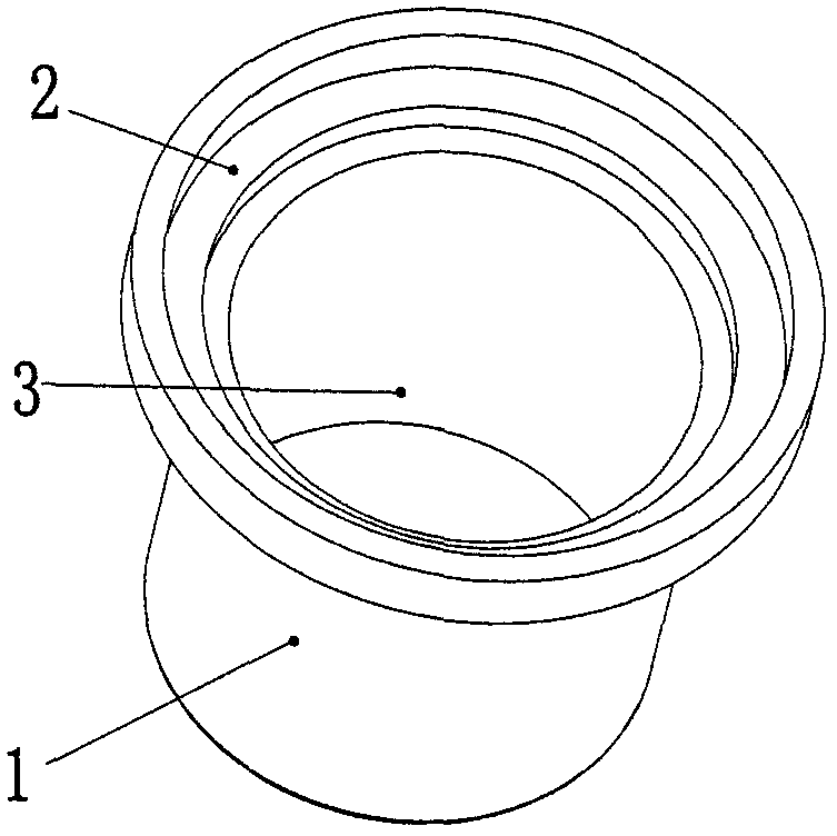
[0021] refer to figure 1 , there is a supporting position 2 and a water leakage cavity 3 on the jacket 1;

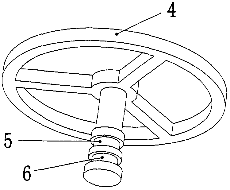
[0022] refer to figure 2 , the support frame 4 has a first positioning groove 5 and a second positioning groove 6;

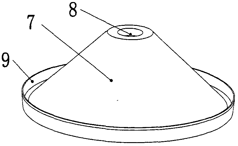
[0023] refer to image 3 , the first water sealing member 7 has a first positioning hole 8 and a first water sealing ring 9;

[0024] refer to Figure 4 , the second water sealing member 10 has a second positioning hole 11 and a second water sealing ring 12;

[0025] Among them, the first water sealing member 7 and the second water sealing member 10 are deformable and resettable thin elastic silica gel sheets, and the cross sections of the first water sealing ring 9 and the second water sealing ring 12 are “V” shapes;

[0026] refer to Figure 5 , Figure 6 , the support frame 4 is on the support position 2, the first positioning hole 8 is in the first positioning groove 5, the second positioning hole 11 is in the second positioning groove 6, the f...


PUM


Abstract

An odor-resistant water leakage device comprises an outer sleeve, a supporting frame, a first water sealing piece and a second water sealing piece. The outer sleeve is provided with a supporting position and a water leakage cavity; the supporting frame is provided with a first positioning groove and a second positioning groove; the first water sealing piece is provided with a first positioning hole, and the second water sealing piece is provided with a second positioning hole; the first water sealing piece and the second water sealing piece are deformable and resettable thin elastic rubber sheets; the supporting frame is arranged on the supporting position, the first positioning hole is formed in the first positioning groove, the second positioning hole is formed in the second positioninggroove, and the first water sealing piece and the second water sealing piece are arranged in the water leakage cavity. When water flow enters the water leakage cavity, the first water sealing piece and the second water sealing piece deform downwards, after the water flow passes through the water leakage cavity, the first water sealing piece and the second water sealing piece reset, and the first water sealing piece and the second water sealing piece block part of the water flow to form a water seal.

Description

technical field [0001] The invention relates to the field of sanitary ware, in particular to an anti-odor water leakage device for a floor drain and a water pipe under a cabinet basin. Background technique [0002] Existing anti-odor leaking devices mainly include bell type, flap type, water-sealed type, and T-shaped sealed anti-odor type. Among them, the bell type is limited to the use area, such as balconies, dry areas other than toilet shower areas, etc., which are rarely used. If no one is at home for a long time, the water-sealed type will also have the disadvantage of losing its deodorant effect after it dries up; as for the flap type and T-sealed deodorant type, if the domestic water discharged has hair, etc. The sealing block is stuck by debris, which will lead to poor sealing, and the deodorant effect will naturally fail. At the same time, these two anti-odor and anti-odor water leakage devices are also very susceptible to mechanical performance. The flap type will ...

Claims


Application Information

Patent Timeline
IPC IPC(8): E03F5/04
Inventor 虞君道
Owner 虞君道
Why Eureka
Try Eureka