Embedded wire stator transferring tool

A technology for transferring workers and stators, which is applied in the field of wire-wire stator transfer tooling, can solve the problems of inter-turn short circuit, mutual collision of wire-wire stators, and deformation of the winding ends of wire-wire stators, so as to reduce the frequency of back-and-forth transfers and improve production. Efficiency, the effect of ensuring product quality

Inactive Publication Date: 2019-05-14
襄阳中车电机技术有限公司
View PDF0 Cites 0 Cited by
  • Summary
  • Abstract
  • Description
  • Claims
  • Application Information

AI Technical Summary

Problems solved by technology

[0002] At present, after the end of the embedded wire stator is bound and shaped, it needs to be transferred to the electrical inspection area and the dipping station. Now, the transfer method is to use a flat transfer tray for the transfer of the embedded wire stator. During the transfer process, the fixed wire stator only relies on When inserting the triangular wooden wedges in the outer circle of the stator with embedded wires, sometimes the placement of the triangular wooden wedges is inappropriate or sometimes the triangular wooden wedges are omitted, which will cause mutual collision between the embedded wire stators, resulting in damage to the enameled wire at the end of the winding Turn-to-turn short circuit, or damage to the outer circle of the iron core that affects the frame, etc., the embedded wire stator may fall from the flat pallet during the transfer process, causing the end of the embedded wire stator winding to be deformed or even scrapped

Method used


Image

  • Embedded wire stator transferring tool

Examples


Embodiment Construction

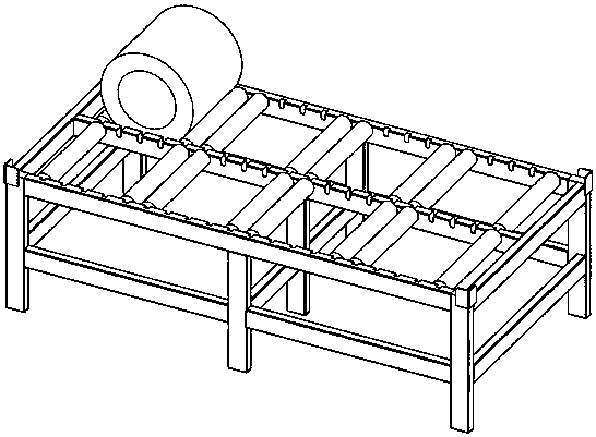
[0010] Such as figure 1 As shown, the present invention comprises integral frame 1, roller 2; Integrated frame 1 is a rectangular frame formed by the welding combination of upright column and cross column, and upright column and cross column adopt carbon steel square pipe to make; On integral frame 1 There are two or three horizontal columns parallel to each other along the length direction on the end surface. figure 1 The middle is set as three, and the three horizontal columns are two of which are respectively arranged on the two long sides of the overall frame 1, one is located in the middle of the two, and the three columns are parallel to each other; between two or three horizontal columns The upper surface is evenly opened with "U"-shaped notches 4, which are used to place and fix the roller 2. The "U"-shaped notches 4 on two or three horizontal columns correspond to each other, so that the rollers placed on them can 2 are parallel to each other; roller 2 is composed of...


PUM


Abstract

The invention discloses an embedded wire stator transferring tool, and relates to tools for protection in the embedded wire stator transferring process and paint knob removal after embedded wire stator painting. The embedded wire stator transferring tool mainly solves the problems that during current transferring, a plane transferring tray is adopted, triangular wood wedges are plugged to the outer circles of embedded wire stators for fixing, if the placement positions of the triangular wood wedges are improper or omission happens, mutual collisions happen between the embedded wire stators, consequently, varnished wires at the end portions of windings are impacted, and the turn-to-turn short circuit is caused or the embedded wire stators falls down from the plane tray, and consequently theend portions of the windings of the embedded wire stators deform. According to the embedded wire stator transferring tool, the upper end face of an integral frame is provided with parallel rollers, and the rollers are placed in U-shaped notches in the upper end of the integral frame through shafts at the two ends of the rollers to be fixed. By means of the embedded wire stator transferring tool,mutual collisions of the embedded wire stators in the transferring process are avoided, the structure is firm, after the embedded wire stators are discharged out of an oven, the embedded wire statorscan be hoisted to the tool to be subjected to paint knob cleaning, and the steps that the embedded wire stators are placed on a workbench to be cleaned and then are transferred to the transferring tool are reduced.

Description

technical field [0001] The invention relates to a transfer tool for a wire-embedded stator, in particular to a tool for protecting the wire-embedded stator during transfer and for cleaning the lacquer tumor after the wire-embedded stator is painted. technical background [0002] At present, after the end of the embedded wire stator is bound and shaped, it needs to be transferred to the electrical inspection area and the dipping station. Now, the transfer method is to use a flat transfer tray for the transfer of the embedded wire stator. During the transfer process, the fixed wire stator only relies on When inserting the triangular wooden wedges in the outer circle of the stator with embedded wires, sometimes the placement of the triangular wooden wedges is inappropriate or sometimes the triangular wooden wedges are omitted, which will cause mutual collision between the embedded wire stators, resulting in damage to the enameled wire at the end of the winding In the case of in...

Claims


Application Information

Patent Timeline
Patent Type & Authority Applications(China)
IPC IPC(8): B65D6/08B65D25/10
Inventor 李荡曾巍彭杨
Owner 襄阳中车电机技术有限公司
Why Eureka
Try Eureka