Overcurrent protection circuit with self-checking function

A technology of overcurrent protection circuit and function, which is applied in the direction of emergency protection circuit device, emergency protection device with automatic disconnection, protection reacting to overcurrent, etc., and can solve problems such as high material cost, limited practical range, and no protection , to achieve the effect of optimizing the design scheme, reducing the design cost, and improving the size of the ripple

Inactive Publication Date: 2019-05-10
JEE AUTOMATION EQUIP SHANGHAI CO LTD
View PDF5 Cites 3 Cited by
  • Summary
  • Abstract
  • Description
  • Claims
  • Application Information

AI Technical Summary

Problems solved by technology

[0006] In the two existing technical schemes, voltage dividing resistors and LDOs are used to output corresponding reference voltages, which requires high precision of the resistors. Adding an additional LDO also increases the cost of materials; when it is necessary to adjust the overcurrent detection When the threshold is reached, the hardware circuit needs to be changed, and the practical range of this solution is strictly limited; when the overcurrent detection reference voltage deviates, the CPLD cannot recognize it, and it is prone to false triggering and non-protection, which greatly increases the risk of controller failure ;The generation of over-current detection reference is strictly controlled by the power-on sequence. When the system is initialized, it is prone to the risk of false alarm over-current

Method used


Image

  • Overcurrent protection circuit with self-checking function
  • Overcurrent protection circuit with self-checking function
  • Overcurrent protection circuit with self-checking function

Examples


Embodiment Construction

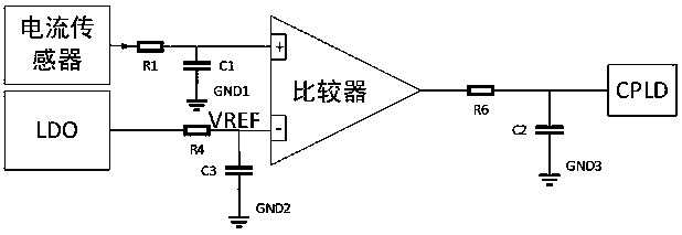
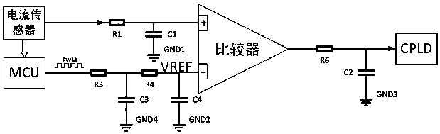
[0025] Such as image 3 As shown, a kind of overcurrent protection circuit with self-checking function of the present invention comprises current sensor, MCU, comparator and CPLD, and the output terminal of described current sensor is respectively connected to the positive phase input terminal of MCU and comparator, and the current The sensor is connected to the non-inverting input terminal of the comparator through an RC filter circuit composed of a resistor R1 and a capacitor C1. The MCU is connected to the inverting input terminal of the comparator through a second-order RC filter circuit, and the MCU sends out PWM with a set fixed duty cycle, and inputs the reference voltage VREF to the comparator through a second-order RC filter circuit, and the second-order RC filter circuit is composed of Composed of resistor R3, capacitor C3, resistor R4, and capacitor C4. The output terminal of the comparator is connected to the CPLD through an RC filter circuit composed of a resisto...


PUM


Abstract

The invention discloses an overcurrent protection circuit with a self-checking function. The circuit comprises a current sensor, an MCU, a comparator and a CPLD, wherein the output end of the currentsensor is connected with the non-inverting input ends of the MCU and the comparator; the MCU is connected with the inverting input end of the comparator through a multi-order RC filtering circuit; theMCU sends out set PWM with a fixed duty ratio and inputs a reference voltage VREF to the comparator through the multi-order RC filtering circuit; and the output end of the comparator is connected with the CPLD. By using the scheme of the multi-order RC filtering circuit, the adjustability of a reference voltage VREF threshold is achieved, and the ripple wave size of the reference voltage VREF canbe better controlled; the magnitude of the reference voltage VREF can be adjusted in real time without change of a hardware circuit; the MCU can monitor the reference voltage VREF in real time, so that the safety of a system is guaranteed; and other voltage sources do not need to be introduced as the reference voltage VREF, so that the design cost and the power consumption of the system are reduced, the design scheme is optimized, and a fault is not misreported in a system initialization process according to the improved scheme.

Description

technical field [0001] The invention relates to the technical field of overcurrent detection of circuits, in particular to an overcurrent protection circuit with a self-test function. Background technique [0002] Due to the rapid development of new energy vehicles, the performance requirements for automotive electronics are getting higher and higher. In particular, the motor has more and more stringent requirements on the control strategy and fault diagnosis of the controller. The platform design of new energy vehicle motor controller is the current development trend. The IGBT overcurrent detection and protection strategy is one of the important means to ensure the safe operation and life of the motor controller. Designing an overcurrent protection scheme suitable for different powers has become a topic of common discussion. [0003] At present, the existing overcurrent protection circuit schemes are mainly as follows: [0004] 1. If figure 1 As shown, the reference vol...

Claims


Application Information

Patent Timeline
Patent Type & Authority Applications(China)
IPC IPC(8): H02H7/085H02H3/08H02H3/00
Inventor 刘蕾张守先马天顺
Owner JEE AUTOMATION EQUIP SHANGHAI CO LTD
Why Eureka
Try Eureka