
Radar antenna array expansion and contraction mechanism

A technology of radar antennas and antennas, which is applied in the direction of folding antennas and retractable units, etc., can solve the problems of the limitation of the total size of antennas in the number of sub-arrays, manual hoisting, etc., and achieve easy installation and local maintenance, high precision, and good motion stability Effect

Active Publication Date: 2019-05-10
CHINA ELECTRONIC TECH GRP CORP NO 38 RES INST
View PDF7 Cites 1 Cited by
  • Summary
  • Abstract
  • Description
  • Claims
  • Application Information

AI Technical Summary

Problems solved by technology

However, after the array is transported in pieces, the on-site assembly and erection often need to be hoisted manually, and the flipping and folding of the antenna array has certain restrictions on the number of sub-arrays and the total size of the antenna.

Method used


Image

  • Radar antenna array expansion and contraction mechanism
  • Radar antenna array expansion and contraction mechanism
  • Radar antenna array expansion and contraction mechanism

Examples


Embodiment 1

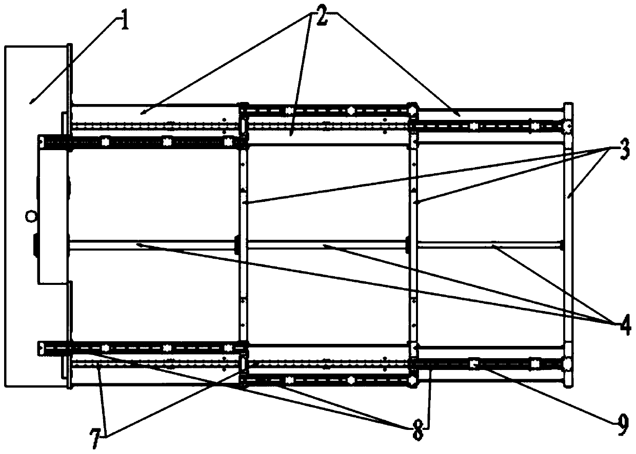
[0023] Such as figure 1 as shown, figure 1 It is a structural view of the radar antenna array retractable mechanism of the present invention; the radar antenna array retractable mechanism includes an antenna back frame 1, a plurality of telescopic arms 2, a support rod 3, a plurality of oil cylinders 4 and a guide device, the The telescopic support arms 2 are respectively arranged on both sides of the antenna back frame 1, the telescopic support arms 2 are arranged in pairs, and the corresponding two telescopic support arms 2 are connected by the support rod 3, and on the antenna back frame 1. Two adjacent telescopic arms 2 on the same side are socketed, and the integrated telescopic arms 2 are socketed in the rectangular cylinder of the antenna back frame 1 as a whole, so as to make full use of the antenna back frame 1; the support rods 3 are connected to the corresponding oil cylinders 4, and the oil cylinders 4 can realize the expansion and retraction of the adjacent teles...

Embodiment 2

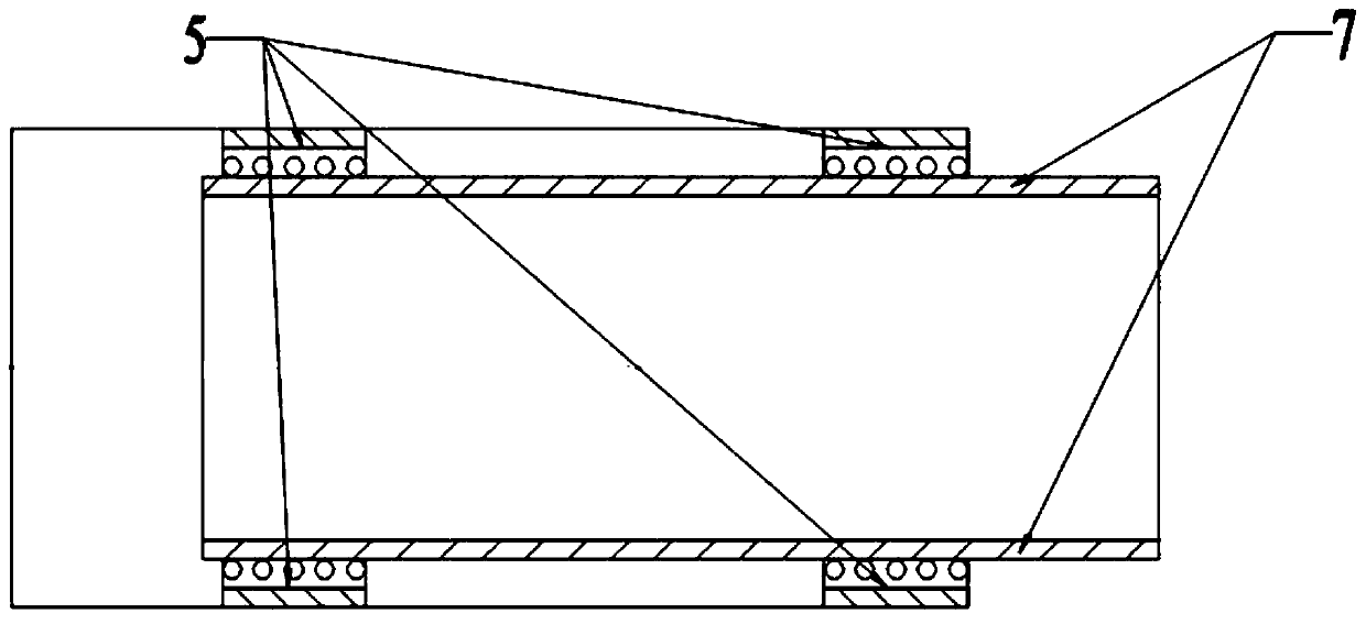
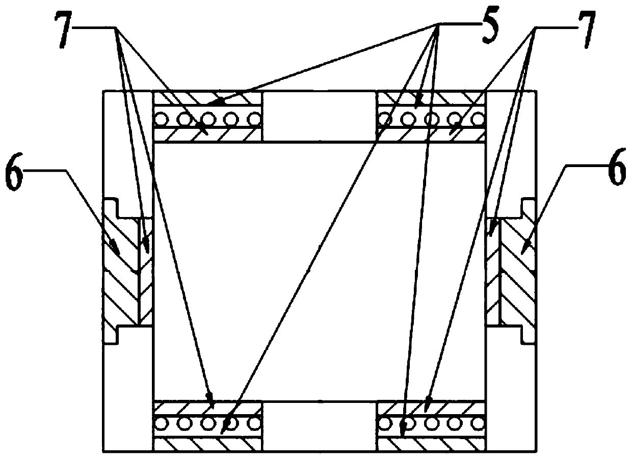
[0032] In this example, Figure 4 It is a partial structural view of Embodiment 2 of the radar antenna array deployment mechanism of the present invention; the telescopic support arm 2 on one side includes three parts: the first section arm 21, the second section arm 22 and the third section arm 23 , the first section arm 21, the second section arm 22 and the third section arm 23 are all arranged as rectangular cylinders, and the second section arm 22 is nested on the first section arm 21, The third section arm 23 is nested on the second section arm 22, the third section arm 23 is sleeved on the antenna back frame 1, the first section arm 21 and the second section arm The inner guide group is provided between the arms 22 and between the second section arm 22 and the third section arm 23 .

[0033] Preferably, the telescopic support arm is set as a rectangular cylinder, the plane guide rail is embedded on the outer end surface of the telescopic support arm, the installation su...


PUM


Abstract

The present invention provides a radar antenna array expansion and contraction mechanism. The mechanism comprises an antenna back frame, a plurality of telescopic support arms, support rods, a plurality of oil cylinders and guiding devices. The telescopic support arms are respectively arranged on two sides of the antenna back frame; the adjacent telescopic support arms at the same side of the antenna back frame are sleeved; the telescopic support arms are arranged in pairs; the corresponding two telescopic support arms are connected by using the support rod; the radar antenna array expansion and contraction mechanism has a truss structure as a whole; the support rods are connected with the corresponding oil cylinders; the oil cylinder is configured to drive the expansion and contraction mechanism to expand or contract; the adjacent telescopic support arms are provided with the guiding device; and the guiding device is configured to guide the relative movement between the adjacent telescopic support arms. According to the radar antenna array expansion and contraction mechanism provided by the present invention, by using a truss structure of "two rows of multi-stage telescopic support arms+support rods+multi-stage oil cylinders", while ensuring the overall rigidity, the problems of the number of sub-arrays and the total size of the antennas restricted by a turnover mechanism aresolved to some extent, and the automatic erection of large-scale radar antennas are realized.

Description

technical field [0001] The invention relates to the field of antenna unfolding and retracting mechanisms, in particular to a radar antenna array unfolding and retracting mechanism. Background technique [0002] With the increasing development of weapons and equipment, contemporary warfare presents a trend of uncertainty, requiring ground radars to have the ability to quickly transfer, and the requirements for high mobility of ground radars are getting higher and higher. At the same time, the modernization and informatization of weapon systems have determined that radars have increased requirements for target detection range, accuracy, and anti-stealth, and the radar antenna diameter has also continued to increase. When the antenna caliber is large, in order to meet the transportation passability and mobility requirements of the radar antenna, the array is usually assembled and erected on site after the array is transported in blocks, or the antenna array is flipped and folde...

Claims


Application Information

Patent Timeline
Patent Type & Authority Applications(China)
IPC IPC(8): H01Q1/10
Inventor 房景仕陶国灿胡志伟
Owner CHINA ELECTRONIC TECH GRP CORP NO 38 RES INST
Learn More