Ocean current power generation device suitable for underwater unmanned vehicle
A technology of unmanned aerial vehicles and ocean current power generation, which is applied in the fields of hydropower generation, underwater ships, underwater operation equipment, etc., and can solve the problems affecting the power generation effect of vertical axis ocean current energy generation devices, the operating performance and safety of underwater vehicles, and contact Complicated, occupying space inside the aircraft, etc.
- Summary
- Abstract
- Description
- Claims
- Application Information
AI Technical Summary
Problems solved by technology
Method used
Image
Examples
specific Embodiment approach 1
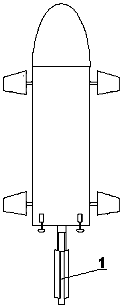
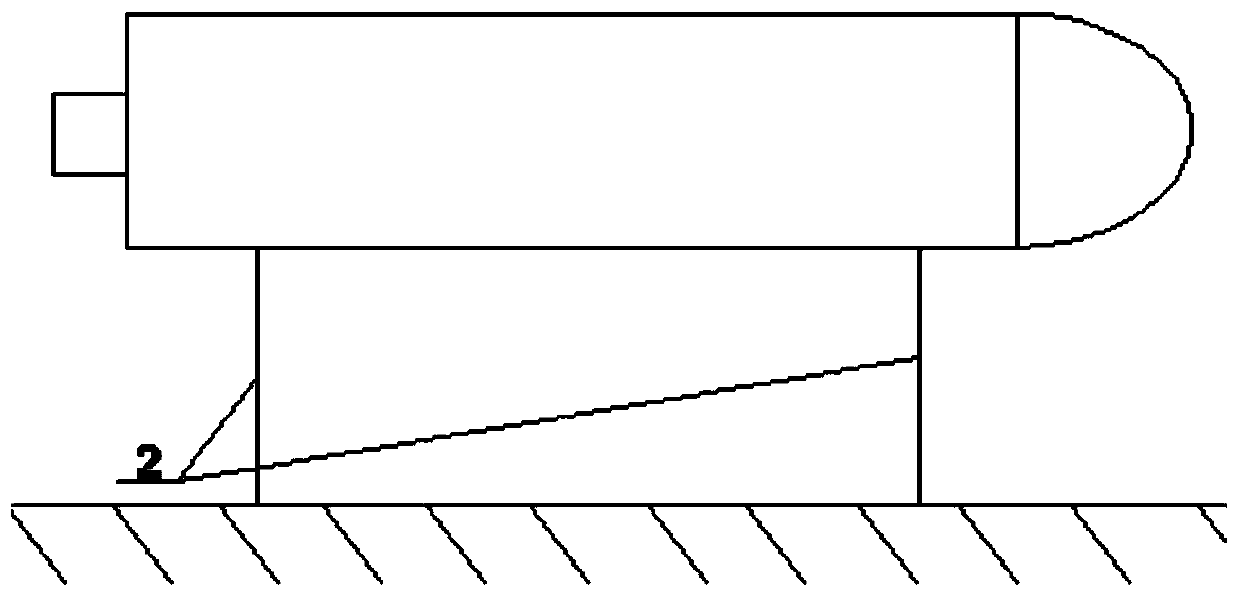
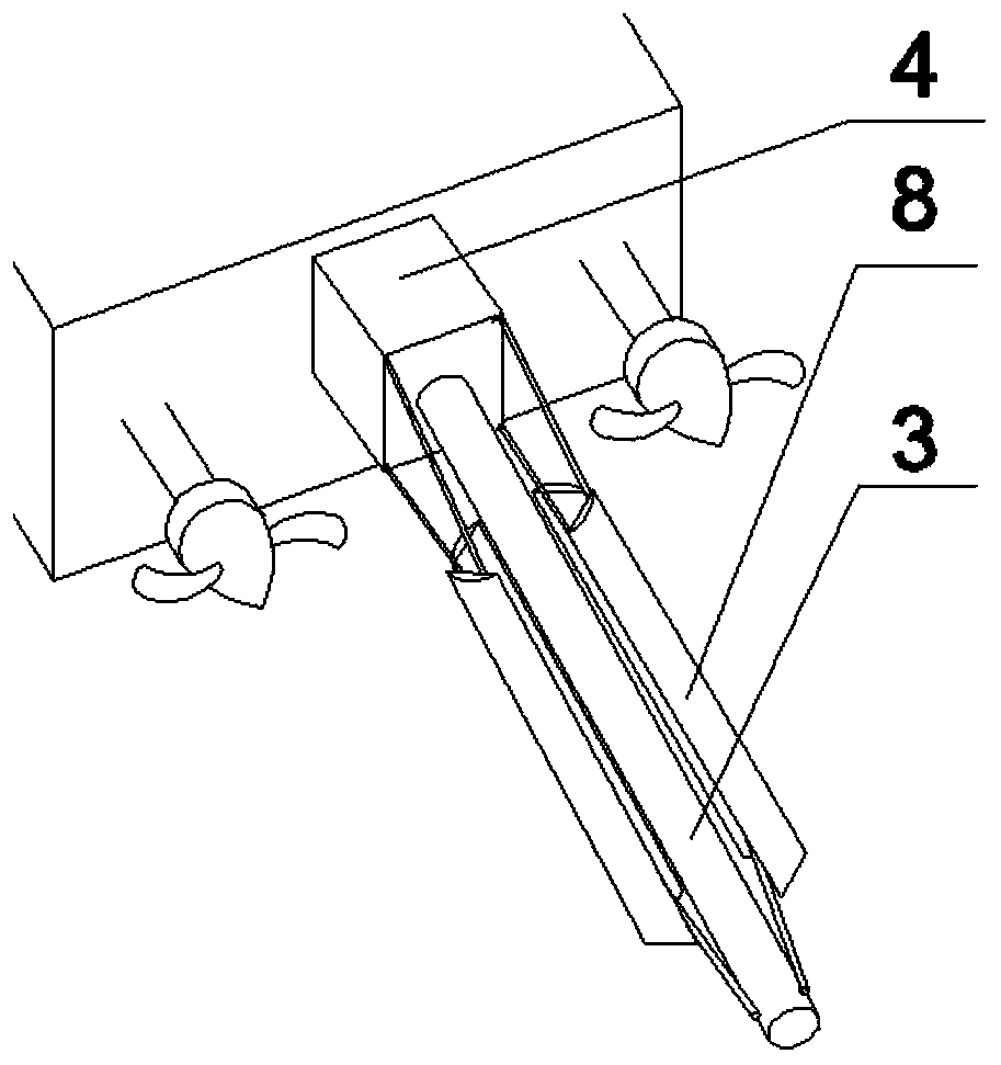
[0027] Specific implementation mode 1: see figure 1 , figure 2 , image 3 , Figure 4 and Figure 5 .
[0028] When the underwater unmanned vehicle is sailing, the overall power generation device is installed in the middle of the two propellers outside the tail end of the underwater unmanned vehicle. The linear motor 4 is close to the outer surface of the tail end of the vehicle. In a contracted state, the permanent magnet generator 9 is close to the inside of the tail end of the aircraft, such as image 3 and 4 shown.
[0029] When the underwater unmanned vehicle needs to be charged, the combination figure 2 , 3 , 4 and 5. First, the underwater unmanned vehicle figure 2 The double anchor chain method is fixed, and then the linear motor 4 moves to the designated position away from the tail end of the aircraft. During the motion of the linear motor 4, the pull rod 5 will push the blade 8 and the arm 7 to move together, and the vertical shaft The blades 8 of the wa...
specific Embodiment approach 2
[0031]Specific implementation mode 2: Participate in Figure 6 , Figure 7 and Figure 8 .
[0032] The contraction and expansion of the power generation device adopts such as Figure 6 The structure shown includes smooth ball 10, hydraulic telescopic arm 11, groove 12 and disk 13, wherein the position of disk 13 is the same as that of linear motor 4 in mode 1, and the position of disk 13 and hydraulic telescopic arm 11 is the same as that of mode 1. The function of the linear motor 4 in 1 is the same. combine Figure 6 , 7 and 8 to illustrate in detail, the hydraulic telescopic arm 11 protruding from the inside of the tail end of the aircraft is fixed to the bottom of the disk 13, and is used to control the contraction and expansion of the blades 8 of the power generation device. There is a circle groove 12 on the upper end of the disk 13, and the smooth bead 10 at one end of the pull rod 5 can move circularly in the groove 12. When the vertical axis type water turbine ...
PUM
 Abstract
Description
Claims
Application Information
 - R&D
- Intellectual Property
- Life Sciences
- Materials
- Tech Scout
- Unparalleled Data Quality
- Higher Quality Content
- 60% Fewer Hallucinations
Browse by: Latest US Patents, China's latest patents, Technical Efficacy Thesaurus, Application Domain, Technology Topic, Popular Technical Reports.
© 2025 PatSnap. All rights reserved.Legal|Privacy policy|Modern Slavery Act Transparency Statement|Sitemap|About US| Contact US: help@patsnap.com


