Eureka AIR delivers breakthrough ideas for toughest innovation challenges, trusted by R&D personnel around the world.

Mechanical paw clamping force detection device

A technology of mechanical grippers and detection devices, applied in the detection field, can solve the problems of affecting workpiece grasping, small guide rod size, and failure to press back normally, and achieve the effects of simple structure, easy fastening, and easy use

Active Publication Date: 2019-05-10
SUZHOU JODELL ROBOTICS CO LTD
View PDF10 Cites 0 Cited by
  • Summary
  • Abstract
  • Description
  • Claims
  • Application Information

AI Technical Summary

Problems solved by technology

[0005] (1) Accessories such as guide rods and load cells must be installed on each finger, resulting in complex structure and high quality of the mechanical gripper;
[0006] (2) In order to adapt to the installation of accessories such as guide rods and load cells, the size of the manipulator claws must be large and cannot be miniaturized, and its application is limited;
[0007] (3) In order to detect the clamping force online, the guide rod needs to pass through the guide hole on the manipulator claw to extend out of the end face of the gripper. When it is used for many times or improperly operated, the guide rod is prone to jamming and cannot be pressed back normally, which will affect the gripping of the workpiece. Pick;
[0008] (4) The size of the guide rod is small, when the grasping position deviates, the gripper cannot detect the clamping force
[0009] In summary, the current method of online detection of the clamping force of the manipulator will cause the manipulator to have shortcomings such as large mass, complex structure, and low detection effect. It is an effective solution to use a detection device to detect the clamping force of the manipulator before use. However, there is currently no manipulator clamping force detection device with simple structure, reasonable design, reliable performance, wide application, large transmission force, easy operation, and high detection accuracy.

Method used


Image

  • Mechanical paw clamping force detection device
  • Mechanical paw clamping force detection device
  • Mechanical paw clamping force detection device

Examples


Embodiment Construction

[0035] In order to enable those skilled in the art to better understand the solutions of the present invention, the technical solutions in the embodiments of the present invention will be described clearly and completely with reference to the accompanying drawings in the embodiments of the present invention. Obviously, the described embodiments are only It is a part of the embodiments of the present invention, not all the embodiments. Based on the embodiments of the present invention, all other embodiments obtained by those of ordinary skill in the art without creative work shall fall within the protection scope of the present invention.

[0036] It should be noted that the terms "first" and "second" in the specification and claims of the present invention and the above-mentioned drawings are used to distinguish similar objects, and not necessarily used to describe a specific sequence or sequence. It should be understood that the data used in this way can be interchanged under ap...


PUM


Abstract

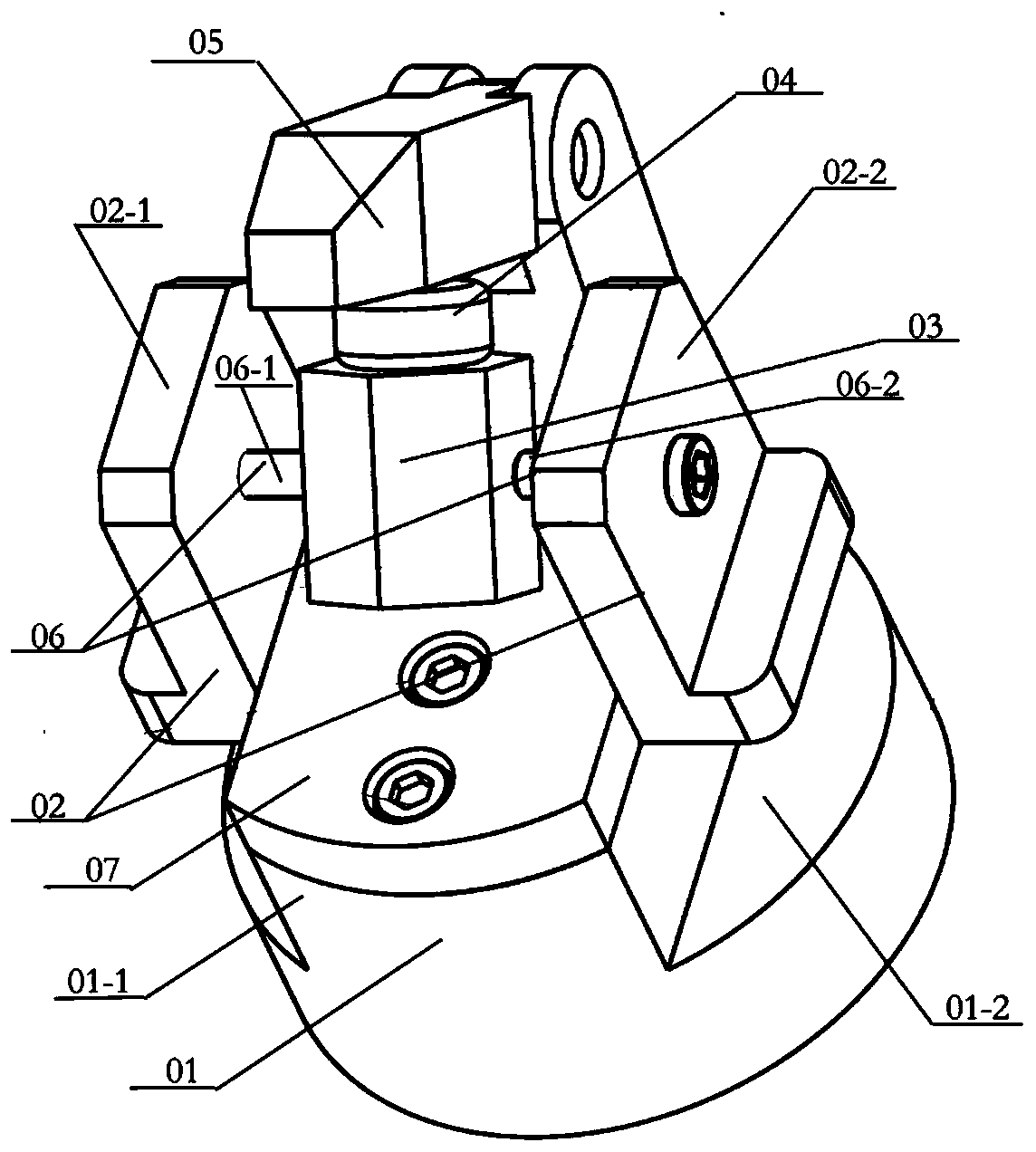
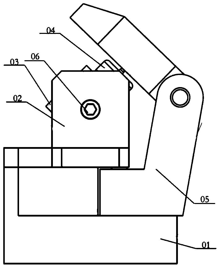
The invention discloses a mechanical paw clamping force detection device. The mechanical paw clamping force detection device is characterized by comprising a base, a supporting part, a support and a force detection part, wherein the supporting part is vertically and fixedly connected with the base, and the supporting part comprises a first supporting part and a second supporting part which are arranged in parallel; the support is arranged between the first supporting part and the second supporting part; and the force detection part is arranged on the support. The detection device has the advantages of being simple in structure and easy to use, and capable of being used for detecting the clamping force of mechanical paws in different forms and the like.

Description

Technical field [0001] The invention relates to the field of detection, in particular to a device for detecting the clamping force of a manipulator claw. Background technique [0002] The manipulator claw is an automatic operation device that can imitate some action functions of human hands to realize grasping, transporting workpieces or operating tools as required, and can replace humans to complete various operations on industrial production lines. Manipulator claws are generally used together with mechanical arms to form an industrial robot system. As the end-executing part of the robot system, the performance of the manipulator claw directly affects or even determines the effect of the robot system in grasping the target and executing the load operation, which is very important for the industrial robot system. [0003] The degree of clamping of the manipulator gripper to the workpiece is very important to its realization function. Obtaining the clamping force of the manipulato...

Claims


Application Information

Patent Timeline
IPC IPC(8): B25J9/16B25J19/00
Inventor 介党阳
Owner SUZHOU JODELL ROBOTICS CO LTD
Why Eureka
Eureka Blog
Learn More