
Protection device for electrical switch

A technology for protection devices and electrical switches, applied in the direction of electric switches, circuits, electrical components, etc., can solve the problems of affecting safety, affecting switch operation, and the switch body is vulnerable to water splashing, so as to achieve the effect of safe use and leakage protection

Inactive Publication Date: 2019-05-07
YONGJIA YABIS TECH CO LTD
View PDF0 Cites 0 Cited by
  • Summary
  • Abstract
  • Description
  • Claims
  • Application Information

AI Technical Summary

Problems solved by technology

[0002] Commonly used electrical switches such as rotary switches, push button switches, and wave switches, etc., need to be fixed on the electrical body when in use, and their operating parts are exposed, such as the rotary handle of the knob switch, the pressing handle of the push button switch, and the toggle switch. The toggle handle of the switch is exposed, which is easy to cause misoperation due to bumping
[0003] The exposed switch body is vulnerable to water splashes, rendering the entire switch useless
When the switch itself leaks electricity, if the entire electrical appliance is not well grounded, it is easy to make the entire electrical appliance electrified, which affects the safety of use.
At the same time, the general switch protection components affect the operation of the switch, which is very inconvenient

Method used


Image

  • Protection device for electrical switch
  • Protection device for electrical switch

Examples


Embodiment Construction

[0015] The following will clearly and completely describe the technical solutions in the embodiments of the present invention with reference to the accompanying drawings in the embodiments of the present invention. Obviously, the described embodiments are only some, not all, embodiments of the present invention. Based on the embodiments of the present invention, all other embodiments obtained by persons of ordinary skill in the art without making creative efforts belong to the protection scope of the present invention.

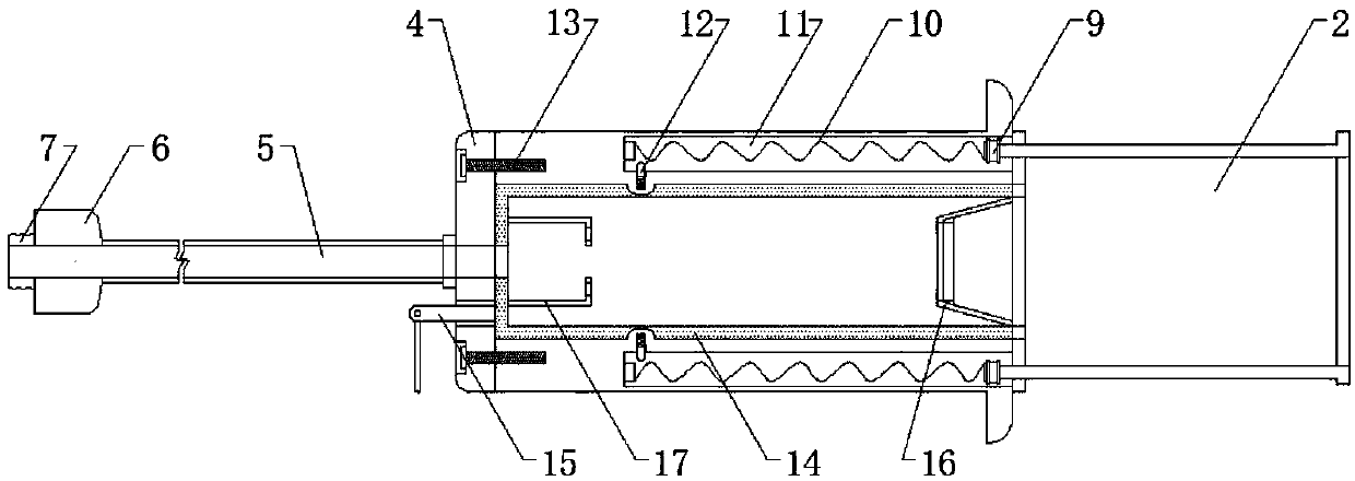
[0016] see figure 1 and figure 2 , figure 1 It is a schematic cross-sectional view of the present invention, figure 2 It is a schematic diagram of the appearance of the present invention. A protection device for an electrical switch, which includes a cylinder body 1 and a support rod 5, one side of the body of the cylinder body 1 is fixed with a bottom plate 4 by bolts and the other side of the body is sleeved with a protective sleeve 2, the cylinder body...


PUM


Abstract

The invention discloses a protection device for an electrical switch. The protection device comprises a cylinder body and a support rod, a bottom plate is fixed at one side, of the cylinder body through bolts, the internal portion of the body at the other side is sleeved with a protection cylinder, the outer edge of one side, far away from the cylinder, of the protection cylinder is connected witha transparent protection cover through a hinge, a support base is welded and fixed at one side, far away from the bottom plate, of the support plate, a protection cylinder body is movably installed in a mounting cavity arranged at one side, close to the protection cylinder, of the internal portion of the cylinder body, a spacing ring is welded and fixed at one end of a light spring body spring wire, the other end of the spring wire is welded and fixed at the bottom portion of the mounting cavity, a clamping block is connected with the internal portion of a mounting groove arranged close to the bottom portion of the mounting cavity of the cylinder body through a spring. An aluminum current-conducting plate is inlaid and installed in the cylinder, and has a cylindrical shape. According to the protection device for the electrical switch, the internally installed aluminum current-conducting plate guides the leakage to the ground, and the usage safety is high.

Description

technical field [0001] The invention belongs to the technical field of switch protection devices, and in particular relates to a protection device for electrical switches. Background technique [0002] Commonly used electrical switches such as rotary switches, push button switches, and wave switches, etc., need to be fixed on the electrical body when in use, and their operating parts are exposed, such as the rotary handle of the knob switch, the pressing handle of the push button switch, and the toggle switch. The toggle handle of the switch is exposed, which is easy to cause misoperation due to bumping. [0003] The exposed switch body is vulnerable to water splashes, rendering the entire switch useless. When the switch itself leaks electricity, if the entire electrical appliance is not well grounded, it will easily make the entire electrical appliance electrified, which will affect the safety of use. At the same time, the general switch protection component affects the o...

Claims


Application Information

Patent Timeline
Patent Type & Authority Applications(China)
IPC IPC(8): H01H9/06
Inventor 胡恩卫季利杰
Owner YONGJIA YABIS TECH CO LTD
Learn More