
A detection method, system and device for transformer oil cooling circuit

A technology of cooling circuit and transformer oil, which is applied in the detection system and device of transformer oil cooling circuit, and the detection field of transformer oil cooling circuit, which can solve the problems of increasing the resistance of circulation pipeline, reducing the fluidity of cooling oil, and the risk of system cooling , to achieve the effect of reducing false alarms, avoiding uncertainty, and improving detection reliability

Active Publication Date: 2021-10-26
ZHUZHOU ELECTRIC LOCOMOTIVE CO LTD
View PDF6 Cites 0 Cited by
  • Summary
  • Abstract
  • Description
  • Claims
  • Application Information

AI Technical Summary

Problems solved by technology

However, the way of judging whether the oil pump is working normally through the oil flow relay has certain limitations. When the oil viscosity is low and the fluidity is good, the oil flow relay can well reflect the working state of the oil pump; , In the case of poor fluidity, when the oil flow velocity is not enough to make the force on the blades of the oil flow relay overcome the resistance of the damping spring, the oil flow relay cannot effectively reflect the actual working state of the oil pump, which will cause the oil flow relay to fail and the oil flow will Fault false alarm
And in the case of a large amount of leakage or blockage in the oil circulation pipeline, the oil flow relay cannot reflect the failure state of the pipeline
In addition, judging whether the oil pump is working normally through the flowmeter also has certain limitations, because the flowmeter will increase the resistance in the circulation pipeline, and the flowmeter will further reduce the flow of cooling oil in the case of high oil viscosity and poor fluidity Sexuality, which brings certain risks to the cooling of the system

Method used


Image

  • A detection method, system and device for transformer oil cooling circuit
  • A detection method, system and device for transformer oil cooling circuit
  • A detection method, system and device for transformer oil cooling circuit

Examples


Embodiment Construction

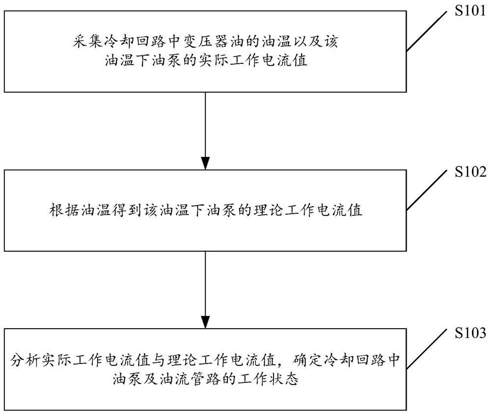
[0054] The core of the present invention is to provide a transformer oil cooling circuit detection method, system, device, electric locomotive and computer-readable storage medium, which can accurately detect the working state of the transformer oil cooling circuit, and fully and truly reflect the oil pump and oil flow tube. The operating conditions of the road can be reduced to reduce false alarms and improve detection reliability.

[0055]In order to make the purpose, technical solutions and advantages of the embodiments of the present invention clearer, the technical solutions in the embodiments of the present invention will be clearly and completely described below in conjunction with the drawings in the embodiments of the present invention. Obviously, the described embodiments It is a part of embodiments of the present invention, but not all embodiments. Based on the embodiments of the present invention, all other embodiments obtained by persons of ordinary skill in the a...


PUM


Abstract

The invention discloses a detection method for a transformer oil cooling circuit, comprising: collecting the oil temperature of the transformer oil in the cooling circuit and the actual working current value of the oil pump at the oil temperature; The theoretical working current value of the oil pump; analyzing the actual working current value and the theoretical working current value to determine the working state of the oil pump and the oil flow pipeline in the cooling circuit. The detection method can accurately detect the working state of the oil pump and the oil flow pipeline in the cooling circuit, comprehensively and truly reflect the operation conditions of the oil pump and the oil flow pipeline, reduce fault false alarms, and improve detection reliability. The invention also discloses a transformer oil cooling circuit detection system, device, electric locomotive and computer-readable storage medium, all of which have the above-mentioned technical effects.

Description

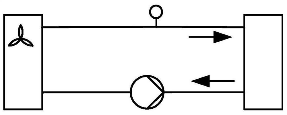
technical field [0001] The invention relates to the technical field of locomotive transformer management, in particular to a detection method for a transformer oil cooling circuit; and also relates to a detection system and device for a transformer oil cooling circuit, an electric locomotive and a computer-readable storage medium. Background technique [0002] The cooling method of the main transformer of an electric locomotive is to pump the transformer oil through an oil pump to a forced air cooling tower for cooling, and then return it to the transformer. If the oil pump cannot work normally, the temperature rise of the transformer may be abnormal during operation, so the oil pump needs to be monitored. In order to monitor the working state of the oil pump, an oil flow relay or a flow meter is usually installed in the oil circulation pipeline to judge whether the oil pump is working normally. However, the way of judging whether the oil pump is working normally through th...

Claims


Application Information

Patent Timeline
Patent Type & Authority Patents(China)
IPC IPC(8): G01R31/00F04B51/00
Inventor 樊运新成本权王位康明明李辉王威何小威秦庆民盛利
Owner ZHUZHOU ELECTRIC LOCOMOTIVE CO LTD
Learn More