Motor based on disturbance compensation position system

A technology of disturbance compensation and motor casing, which is applied in the direction of connection with control/drive circuits, electrical components, electromechanical devices, etc., which can solve the inconvenience of visually observing the working conditions of the motor, the poor heat dissipation effect of the fan on the motor casing, and low maintenance efficiency. problems, to achieve the effect of improving the efficiency and quality of maintenance, improving the quality of ventilation and heat dissipation, and promoting air circulation

Active Publication Date: 2019-03-08
山东孚日电机科技有限公司
View PDF4 Cites 0 Cited by
  • Summary
  • Abstract
  • Description
  • Claims
  • Application Information

AI Technical Summary

Problems solved by technology

[0003] However, the traditional motor based on the disturbance compensation position system is inconvenient to disassemble and repair the internal components of the motor, the repair and maintenance efficiency is low, it is not convenient to observe the working condition of the motor directly, and the cooling effect of the fan on the motor shell is poor.

Method used


Image

  • Motor based on disturbance compensation position system
  • Motor based on disturbance compensation position system
  • Motor based on disturbance compensation position system

Examples


Embodiment Construction

[0027] In order to make the technical means, creative features, goals and effects achieved by the present invention easy to understand, the present invention will be further described below in conjunction with specific embodiments.

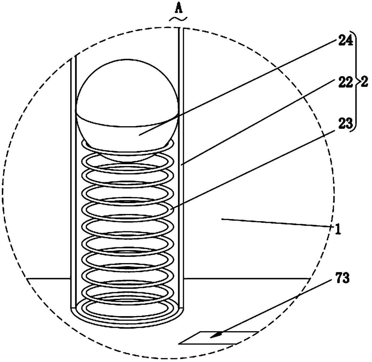
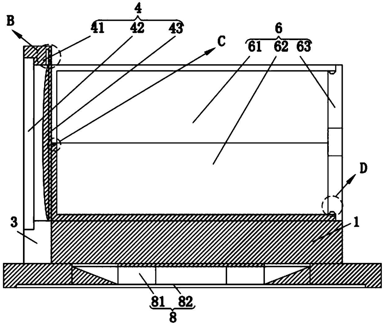
[0028] Such as figure 1 , figure 2 , image 3 with Figure 7 As shown, a motor based on a disturbance compensation position system according to the present invention includes a base plate 1, an indicating structure 2, a junction box 3, a cooling structure 4, a fixing sleeve 5, a motor housing 6, an anti-chip structure 7 and a driving structure 8 The top of the base plate 1 is provided with the motor housing 6 for protecting the motor assembly; the fixed sleeve 5 for fixing the motor housing 6 is slidingly connected to the base plate 1; the inside of the base plate 1 The drive structure 8 for limiting the fixed sleeve 5 is provided; the two ends of the motor housing 6 are respectively provided with the cooling structure 4 for heat dissipation a...


PUM


Abstract

The invention relates to the field of motors, and in particular relates to a motor based on a disturbance compensation position system. The motor based on the disturbance compensation position systemcomprises a bottom plate, an indication structure, a junction box, a cooling structure, a fixing sleeve, a motor housing, an anti-scrap structure and a driving structure; the fixing sleeve used for fixing the motor housing is glidingly connected with the bottom plate; the driving structure used for limiting the fixing sleeve is arranged in the bottom plate; the cooling structure used for heat dissipation and the anti-scrap structure used for preventing the rotating shaft of the motor from being damaged are respectively arranged at two ends of the motor housing; and the indication structure used for observing the vibration condition of the motor is arranged on the bottom plate. According to the motor based on the disturbance compensation position system in the invention, the driving structure is used with the fixing sleeve in a matched manner; therefore, the motor housing is conveniently assembled and disassembled rapidly; the overhaul maintenance efficiency and the quality of internalcomponents of the motor housing are greatly improved; the cooling structure is arranged at the end part of the motor housing, so that circumferential air circulation of the motor housing is promoted;therefore, the ventilation and heat dissipation quality can be greatly improved; and thus, the vibration condition of the motor can be intuitionally observed conveniently through the indication structure.

Description

technical field [0001] The invention relates to the field of motors, in particular to a motor based on a disturbance compensation position system. Background technique [0002] The permanent magnet synchronous motor is a synchronous motor that is excited by a permanent magnet to generate a synchronous rotating magnetic field. The permanent magnet acts as a rotor to generate a rotating magnetic field. The three-phase stator winding reacts through the armature under the action of the rotating magnetic field to induce a three-phase symmetrical current. The permanent magnet synchronous motor Usually it can be controlled for three purposes, namely: torque control using current control, speed control, and position control; torque control is a control process based on speed control and position control, and since current is proportional to torque, torque control is usually used Known as current control, any change in the magnetic flux induced by the stator as the permanent magnet r...

Claims


Application Information

Patent Timeline
Patent Type & Authority Applications(China)
IPC IPC(8): H02K11/33H02K5/20H02K11/20
CPCH02K5/20H02K11/20H02K11/33
Inventor 常康华胡自然苏杰
Owner 山东孚日电机科技有限公司
Why Eureka
Try Eureka