
Mounting Bracket for Blind

a technology for mounting brackets and blinds, applied in the field of mounting brackets, can solve the problems of increasing problems and difficult removal of fascias, and achieve the effect of quick and easy installation and removal, and simple installation

Inactive Publication Date: 2011-05-19
NG PHILIP
View PDF10 Cites 17 Cited by
  • Summary
  • Abstract
  • Description
  • Claims
  • Application Information

AI Technical Summary

Benefits of technology

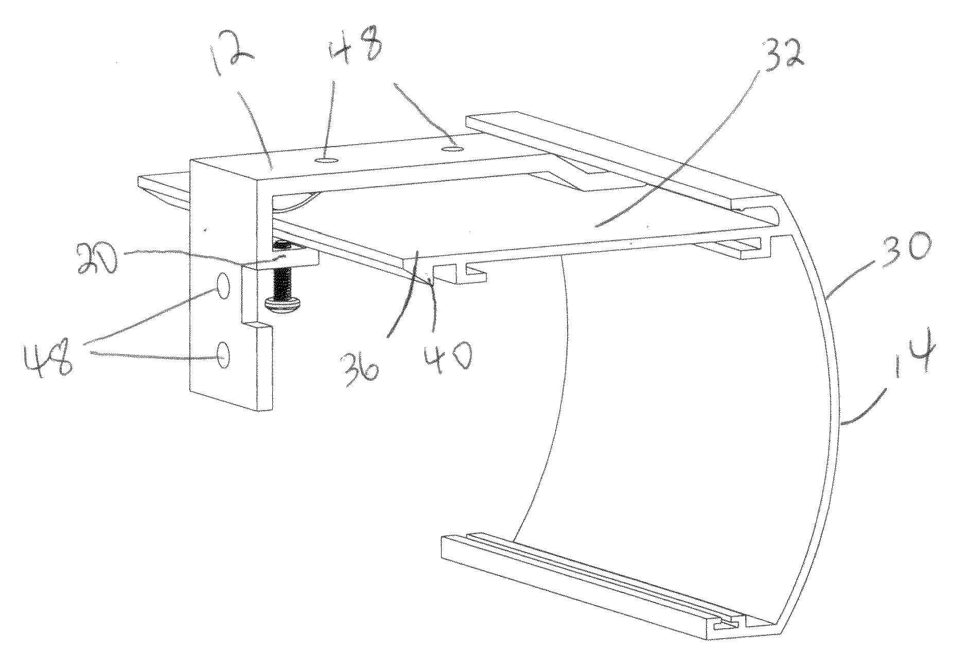
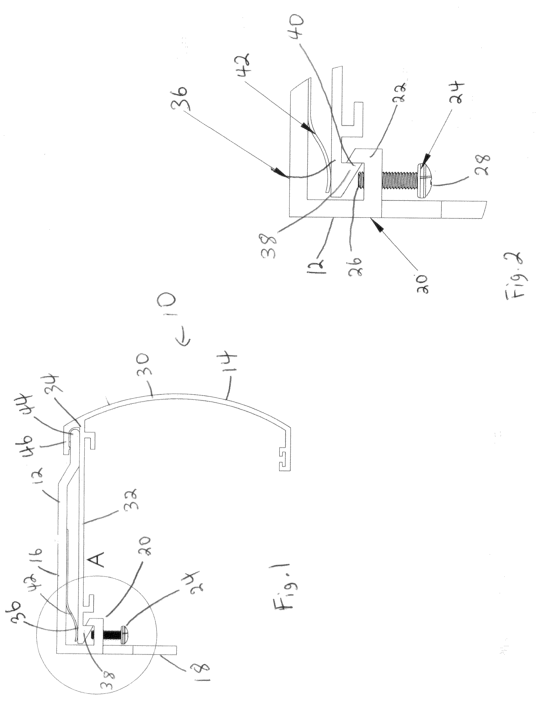
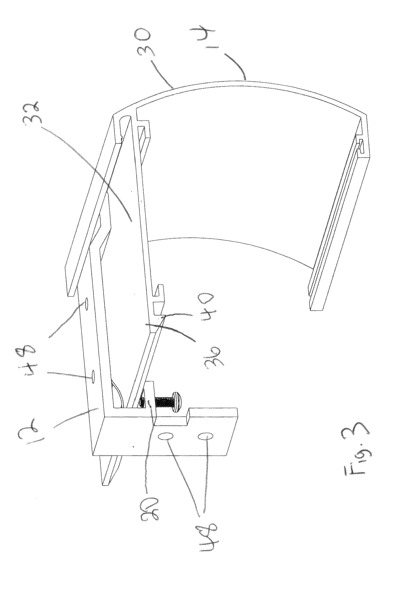
[0003]In accordance with one aspect of the invention, there is provided a fascia and mounting bracket combination for a blind which is simple to install and which permits the quick and easy installation and removal of the head portion. The mounting bracket and fascia combination includes a mounting bracket having a first locking element and a fascia having a face portion and an extended leg. The extended leg has a proximal end adjacent the face portion and a distal end opposite the proximal end. The fascia and bracket combination further includes a second locking element formed on the fascia adjacent the distal end of the extended leg, the second locking element configured to mate with the first locking element. A release member is mounted to the mounting bracket adjacent the first locking element, the release member movable between a locked position wherein the release member is clear of the second locking element, and a release position wherein the release member bears against the second locking element sufficiently to disengage the second locking element from the first locking element.

Problems solved by technology

Removing the fascia can be difficult where the head portion covers over or obscures the mounting brackets holding up the fascia.
In the case of very wide blinds the problem is increased because of the awkwardness caused by the length of the fascia and head portion.

Method used


Image

  • Mounting Bracket for Blind
  • Mounting Bracket for Blind
  • Mounting Bracket for Blind

Examples


Embodiment Construction

[0015]Referring firstly to FIG. 1, a fascia and mounting bracket combination made in accordance with the present invention is shown generally as item 10 and consists of mounting bracket 12 and fascia 14. Mounting bracket 12 has elongated arm portion 16 and transverse portion 18. A first locking element 20 is formed on bracket 12, preferably on transverse portion 18. Fascia 14 consists of a member having a face portion 30 and an extended leg portion 32, the leg portion having a proximal end 34 adjacent the face portion 30 and a distal end 36 opposite the proximal end. A second locking element 38 is formed on the distal end 36 of the leg portion. First locking element 20 and second locking element 38 preferably consists of hooks 22 and 40, respectively, which are configured to hook together. A release member 24 is mounted to mounting bracket 12 adjacent locking element 20. Release member 24 is movable between a locked position, as shown in FIG. 2 wherein the release member is clear of...


PUM


Abstract

The invention is a fascia and mounting bracket combination for a blind having a head portion. The mounting bracket and fascia combination includes a mounting bracket having a first locking element and a fascia having a face portion and an extended leg. The extended leg has a proximal end adjacent the face portion and a distal end opposite the proximal end. The fascia and bracket combination further includes a second locking element formed on the fascia adjacent the distal end of the extended leg, the second locking element configured to mate with the first locking element. A release member is mounted to the mounting bracket adjacent the first locking element, the release member movable between a locked position wherein the release member is clear of the second locking element, and a release position wherein the release member bears against the second locking element sufficiently to disengage the second locking element from the first locking element.

Description

FIELD OF THE INVENTION[0001]The invention relates generally to mounting elements for mounting a decorative fascia to the head portion of a blind.BACKGROUND OF THE INVENTION[0002]Most window blinds consist of a fabric (or other) blind suspended from a head portion which is mounted adjacent the top of the window. The head portion can consist of a roller blind assembly (in the case of a roller blind) or some other similar control unit which incorporates the mechanism required to raise and lower the blind. The head portion can be unattractive, therefore a fascia is generally mounted in front of the head portion to present a more pleasant appearance. The fascia may be mounted to mounting brackets which in turn are mounted to the wall or window frame. In many cases, the head portion is also mounted to the mounting brackets making it necessary to remove the fascia in order to remove the head portion. Removing the fascia can be difficult where the head portion covers over or obscures the mo...

Claims


Application Information

Patent Timeline
IPC IPC(8): F16M13/00
CPCE06B9/42E06B9/323
Inventor NG, PHILIP
Owner NG PHILIP
Learn More