Household appliance and door assembly thereof
A technology for household appliances and door components, applied in door/window fittings, wing handles, buildings, etc., can solve the problems of affecting the overall appearance of the facade, lack of creativity and innovation, and the door handles are prone to scratch users, etc., to improve the use of Experience, prevent stuck or even stuck, avoid adverse effects
- Summary
- Abstract
- Description
- Claims
- Application Information
AI Technical Summary
Problems solved by technology
Method used
Image
Examples
Embodiment 1
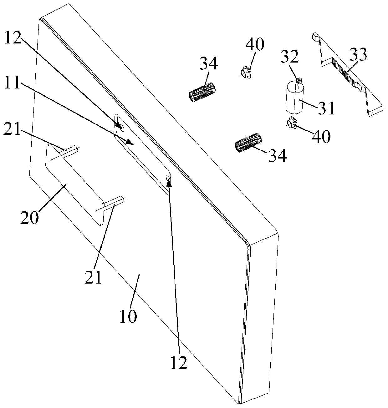
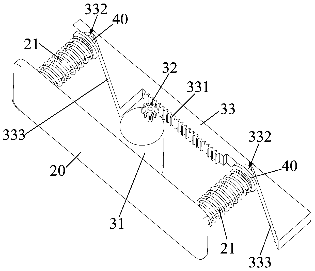
[0066] The door assembly also includes: a driving device, which cooperates with the door handle 20 and is used to drive the door handle 20 to reciprocate relative to the door panel 10 , so that the door handle 20 can automatically extend or retract into the handle groove 11 .
[0067] The setting of the driving device realizes the automatic movement of the door handle 20, so that the door handle 20 can automatically extend out of the handle groove 11 when it needs to be used, and can automatically retract into the handle groove 11 when it is not used, thereby improving the automation degree of the product , full of sense of technology. As for the specific control method of the driving device, it is not specifically limited. For example: buttons or sensing devices can be set on the door handle to control the driving device, or it can be controlled by the knob or other components on the main body of the electrical appliance, or it can be controlled by mobile terminals such as mo...
Embodiment 2
[0096] Embodiment 2 (not shown in the figure)
[0097] The difference from Embodiment 1 is that the rotating part is a gear 32, and the transmission part is a guide rail 33 provided with a rack 331 meshing with the gear 32. The extending direction of the rack 331 is parallel to the moving direction of the door handle 20, and the guide rail 33 The end far away from the driving part is matched with the limiting part 40 .
[0098] Rotating part is gear 32, and transmission part is guide rail 33, and guide rail 33 is provided with rack 331, and then rack 331 is meshed with gear 32, can convert the rotary motion of driving member into linear motion; The direction of motion of the door handle 20 is parallel to each other, and the end of the guide rail 33 away from the driving part is matched with the limiter 40, then the linear movement of the guide rail 33 can directly drive the limiter 40 to move linearly so that the door handle 20 stretches out of the handle groove 11 , and then...
Embodiment 3
[0099] Embodiment three (not shown in the figure)
[0100] The difference from Embodiment 1 is that the rotating part is a screw, the transmission part is a sleeve with internal threads, the sleeve is fitted on the screw and fits with the screw thread, and the end far away from the driving part is matched with the limiter 40 .
[0101] The rotating part is a screw, and the transmission part is a sleeve. The sleeve is set on the screw and fits with the screw thread. When the screw rotates with the driving part, the sleeve can move linearly along its axis, and then convert the rotational motion of the driving part into linear motion; the end of the sleeve away from the driving part is matched with the limiter 40, then the linear motion of the sleeve can directly drive the limiter 40 to move linearly so that the door handle 20 stretches out of the handle groove 11, and then the spring 34 or Under the action of the guide rail 33, it retracts into the handle groove 11. At this tim...
PUM
 Abstract
Description
Claims
Application Information
 - R&D
- Intellectual Property
- Life Sciences
- Materials
- Tech Scout
- Unparalleled Data Quality
- Higher Quality Content
- 60% Fewer Hallucinations
Browse by: Latest US Patents, China's latest patents, Technical Efficacy Thesaurus, Application Domain, Technology Topic, Popular Technical Reports.
© 2025 PatSnap. All rights reserved.Legal|Privacy policy|Modern Slavery Act Transparency Statement|Sitemap|About US| Contact US: help@patsnap.com


