Drive power transmission mechanism and electric lock using same

A technology of transmission mechanism and driving force, applied in the field of driving force transmission mechanism and electronic lock, can solve the problems of complicated structure, and achieve the effect of simplifying the overall structure, simple structure and large degree of freedom

Inactive Publication Date: 2019-05-03
NTN CORP
View PDF6 Cites 2 Cited by
  • Summary
  • Abstract
  • Description
  • Claims
  • Application Information

AI Technical Summary

Problems solved by technology

[0006] However, as this reverse input cut-off mechanism, since a worm mechanism with a self-locking function, a speed reduction mechanism with a high deceleration rate, or the input torque is transmitted to the output side and the reverse input torque applied to the output side is locked to cut off The reverse input of torque transmission cuts off the clutch, so there is a problem that the overall structure becomes complicated

Method used


Image

  • Drive power transmission mechanism and electric lock using same
  • Drive power transmission mechanism and electric lock using same
  • Drive power transmission mechanism and electric lock using same

Examples


Embodiment Construction

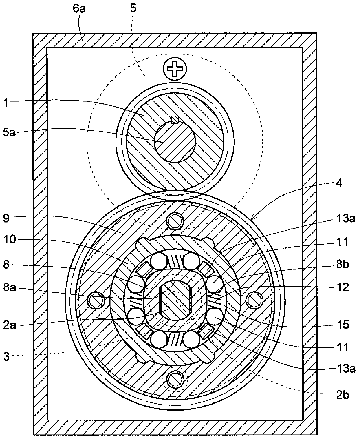
[0024] Embodiments of the present invention will be described below based on the drawings. Figure 1 to Figure 3 shows the first embodiment. Such as figure 1 and figure 2 As shown, the driving force transmission mechanism has: an electric input gear 1 as a first input part; a manual input shaft 2 as a second input part; an output shaft 3 as an output part; An input switching clutch 4 that transmits the rotational driving force of any one of the manual inputs to the manual input shaft 2 to the output shaft 3 ; and a speed reducer 5 provided on the input side of the electric input gear 1 . The electric input gear 1, the inner end portions of the manual input shaft 2 and the output shaft 3, and the input switching clutch 4 are housed in a case (fixed member) that closes the opening on one side of the rectangular box portion 6a with the cover portion 6b. )6. In addition, the speed reducer 5 has no self-locking function, and constitutes a motor with a speed reducer together wi...


PUM


Abstract

This invention prevents co-rotation of an electric input gear (1) when driving from a manual input shaft (2) by way of: an input switching clutch (4) that transmits a rotation driving force applied tothe electric input gear (first input member) (1) or the manual input shaft (second input member) (2) to an output shaft (output member) (3) being provided; a simple structure speed reducer (5) that does not have a self-locking function being provided on the input side of the electric input gear (1); and the running torque required to rotate the electric input gear (1) from the manual input shaft(2) via the input switching clutch (4) being increased to be larger than the running torque required to rotate the output shaft (3) from the manual input shaft (2) via the input switching clutch (4).

Description

technical field [0001] The present invention relates to a driving force transmission mechanism capable of driving an output member to rotate through either a first input member or a second input member by an input switching clutch, and an electronic lock using the driving force transmission mechanism. Background technique [0002] In recent years, in many product fields, appliances and devices that have been manually operated have been promoted to be motorized. However, due to their functions, it is sometimes required to be able to be operated manually during a power failure or when the battery is exhausted. For example, although electronic locks for locking / unlocking without a key are being popularized in entrance doors, it is necessary to be configured so that locking / unlocking with an existing key can also be used in emergencies such as when the electronic lock is powered off. . [0003] The electronic lock as described above includes: a first input member that is driven...

Claims


Application Information

Patent Timeline
Patent Type & Authority Applications(China)
IPC IPC(8): E05B47/00F16D41/10F16D63/00F16H1/06
CPCF16D41/10F16D63/00F16H1/06E05B2047/0026E05B2047/003E05B47/026E05B47/0012E05B2047/0021E05B2047/0086E05B17/0029E05B47/0001E05B47/0665H01H9/283
Inventor 糸见正二
Owner NTN CORP
Why Eureka
Try Eureka