Liquid-phase mechanical stripper

A mechanical peeling and liquid phase technology, applied in grain processing, etc., can solve the problems of low service life of equipment accessories, high operating noise, low output rate, etc., achieve sufficient crushing and peeling, increase output rate, and increase service life Effect

Pending Publication Date: 2019-05-03
赵宁
View PDF9 Cites 3 Cited by
  • Summary
  • Abstract
  • Description
  • Claims
  • Application Information

AI Technical Summary

Problems solved by technology

[0003] The invention proposes a liquid-phase mechanical peeling machine, which solves the problems of low output rate, low service life of equipment accessories and high operating noise in the prior art

Method used


Image

  • Liquid-phase mechanical stripper
  • Liquid-phase mechanical stripper
  • Liquid-phase mechanical stripper

Examples


Embodiment Construction

[0045] The technical solutions in the embodiments of the present invention will be clearly and completely described below in conjunction with the embodiments of the present invention. Apparently, the described embodiments are only some of the embodiments of the present invention, not all of them. Based on the embodiments of the present invention, all other embodiments obtained by persons of ordinary skill in the art without creative efforts fall within the protection scope of the present invention.

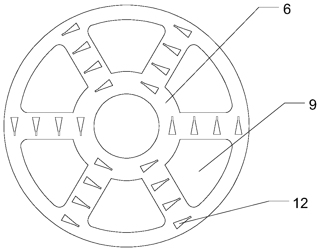
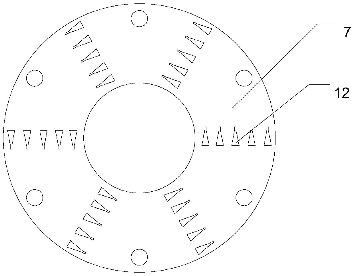
[0046] Such as Figure 1-5 As shown, the present invention proposes a liquid phase mechanical peeling machine,

[0047] including housing 1,

[0048] The rotating shaft 4, the rotating shaft 4 penetrates and is arranged in the housing 1, and the rotating shaft 4 is rotated and arranged in the housing 1,

[0049] There are multiple moving disks 6, the moving disks 6 are arranged in the housing 1, the moving disks 6 and the rotating shaft 4 are fixed,

[0050] The static disk 7, ...


PUM


Abstract

The invention belongs to the technical field of liquid-phase mechanical strippers, and provides a liquid-phase mechanical stripper. The liquid-phase mechanical stripper comprises a shell, a rotating shaft, a plurality of movable discs, a plurality of static discs, a plurality of cutting teeth, a feeding inlet and a discharging outlet, wherein the rotating shaft is arranged in the shell in a penetrating mode and rotationally arranged in the shell, the multiple movable discs are arranged in the shell, the movable discs and the rotating shaft are fixed, the multiple static discs are arranged on the shell, the static discs and the movable discs are arranged sequentially and alternately along the rotating shaft, the multiple cutting teeth are arranged on the movable discs and the static discs correspondingly, and in the rotating process of the movable discs, the cutting teeth on the movable discs pass through gaps between the adjacent cutting teeth on the static discs. Through the technicalscheme, the problems of low output rate, short life of equipment accessories and large operation noise in the prior art are solved.

Description

technical field [0001] The invention belongs to the technical field of liquid-phase mechanical stripping machines, and relates to a liquid-phase mechanical stripping machine. Background technique [0002] At present, the liquid phase stripping machines used in the market generally use a mechanical shaft, and some cutting teeth are installed on the shaft head. Through the high shear force generated by high-speed operation (above 12,000 rpm), the material can be stripped. Due to the high speed of the equipment during use, , it will reduce the service life of the equipment accessories, increase the maintenance cost and processing cost, it is not suitable for long-term operation, and the operation noise is large, and the cutting head cannot be too large because the speed is too high, so the volume of a single device is small, and the production The output rate is low. Contents of the invention [0003] The invention proposes a liquid-phase mechanical peeling machine, which so...

Claims


Application Information

Patent Timeline
IPC IPC(8): B02C18/12B02C18/16B02C18/18B02C18/22B02C18/24
Inventor 赵宁
Owner 赵宁
Why Eureka
Try Eureka