Bidirectional level conversion circuit and bilateral level conversion chip

A technology for converting circuits and levels, which is applied in the direction of bidirectional operation logic circuit coupling/interface, logic circuit interface device, logic circuit connection/interface arrangement, etc., which can solve the problem of increasing chip area and cost, increasing the number of modules and complicating the design issues such as accuracy, to achieve the effect of reducing chip area and cost, reducing the number of modules and design complexity

Pending Publication Date: 2019-04-26
SHANGHAI AWINIC TECH CO LTD
View PDF0 Cites 5 Cited by
  • Summary
  • Abstract
  • Description
  • Claims
  • Application Information

AI Technical Summary

Benefits of technology

This technology improves how signals can be transmitted through an electronic device's communication pathway without adding extra components or increasing its size. It achieves this by converting between different levels at once during each period (the transition). By controlling these stages instead of just sending them down for easy access, it saves on space and costs compared to traditional methods like switches.

Problems solved by technology

This patented describes how levels can convert between different voltages without adding extra components like switches that slow down signals.

Method used


Image

  • Bidirectional level conversion circuit and bilateral level conversion chip
  • Bidirectional level conversion circuit and bilateral level conversion chip
  • Bidirectional level conversion circuit and bilateral level conversion chip

Examples


Embodiment Construction

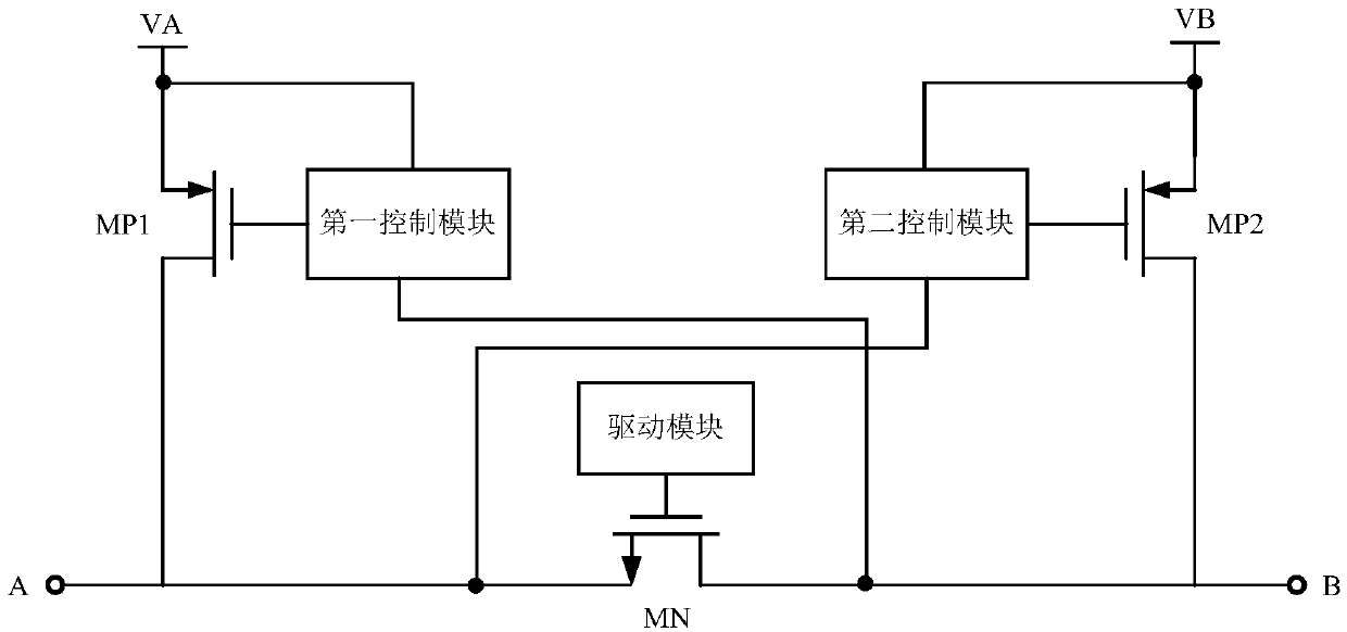
[0041] As mentioned in the background, two pull-up transistors and two control modules need to be added to the existing bidirectional level conversion chip. Such as figure 1 as shown, figure 1 It is a structural schematic diagram of an existing bidirectional level conversion chip. When the first terminal A of the signal transmission terminal MN is flipped from the first level to the second level, the second control module controls the second pull-up transistor MP2 to conduct , pull the second terminal B of the signal transmission terminal MN from the first level to the second level; when the second terminal B of the signal transmission terminal MN is flipped from the first level to the second level, the first control module controls The first pull-up transistor MP1 is turned on to pull the first end A of the signal transmission end MN from the first level to the second level. because figure 1 The two pull-up tubes in the circuit are respectively controlled by the control mo...


PUM


Abstract

The invention provides a bidirectional level conversion circuit and a bilateral level conversion chip. The bilateral level conversion circuit comprises a signal transmission tube, a first pull-up tube, a second pull-up tube and a pull-up control module; a first end of the first pull-up tube is electrically connected with a first voltage end, a second end is electrically connected with the first end of the signal transmission tube; the first end of the second pull-up tube is electrically connected with a second voltage end, and the second end is electrically connected with a second end of the signal transmission tube; a first signal input end of the pull-up control module is electrically connected with the first end of the signal transmission tube, a second signal input end is electricallyconnected with the second end of the signal transmission tube, and an output end is electrically connected with grids of the first pull-up tube and the second pull-up tube and used for outputting first level pulse when any one end of the first end and the second end of the signal transmission tube is overturned as the second level from the first level. Two pull-up tubes in the conversion circuit is controlled by one pull-up control module, the module amount and the design complexity can be reduced, and the chip area and cost can be reduced.

Description


Claims


Application Information

Patent Timeline
Owner SHANGHAI AWINIC TECH CO LTD
Why Eureka
Try Eureka