
Fingerprint identification module and display device

A fingerprint recognition module and fingerprint technology, which are used in character and pattern recognition, acquisition/organization of fingerprints/palmprints, and print image acquisition, etc., can solve the problems of unfavorable development of thin and light display devices, low recognition accuracy, etc., and achieve thin and light. Development, Guaranteed Imaging Effect, Reduced Thickness Effect

Active Publication Date: 2019-04-26
BOE TECH GRP CO LTD +1
View PDF15 Cites 8 Cited by
  • Summary
  • Abstract
  • Description
  • Claims
  • Application Information

AI Technical Summary

Problems solved by technology

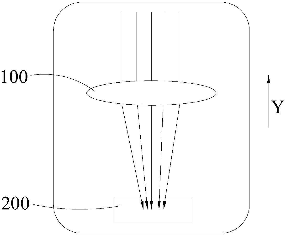
[0004] Generally speaking, the propagation direction of the optical path inside the optical fingerprint recognition module is straight, but according to the imaging principle and the depth of field requirements, the fingerprint recognition module must have enough thickness in the direction of the optical path propagation to ensure the imaging effect , which is not conducive to the development of thinner and lighter display devices
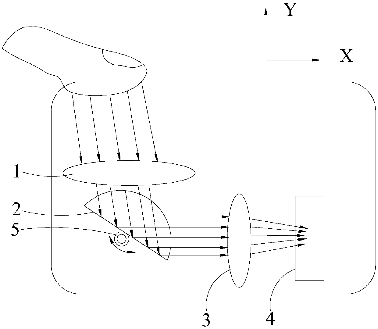
In addition, since different users or the same user may press the fingerprint area at different angles at different times, the optical fingerprint recognition module also has the problem of low recognition accuracy.

Method used


Image

  • Fingerprint identification module and display device
  • Fingerprint identification module and display device
  • Fingerprint identification module and display device

Examples


Embodiment Construction

[0041] Example embodiments will now be described more fully with reference to the accompanying drawings. Example embodiments may, however, be embodied in many forms and should not be construed as limited to the embodiments set forth herein; rather, these embodiments are provided so that this application will be thorough and complete, and will fully convey the concept of example embodiments to those skilled in the art. The same reference numerals in the drawings denote the same or similar structures, and thus their detailed descriptions will be omitted.

[0042] Although relative terms such as "upper" and "lower" are used in this specification to describe the relative relationship of one component of an icon to another component, these terms are used in this specification only for convenience, for example, according to the description in the accompanying drawings directions for the example described above. It will be appreciated that if the illustrated device is turned over s...


PUM


Abstract

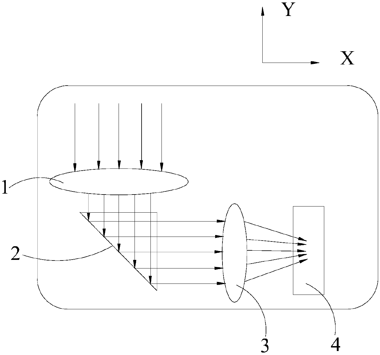
The invention relates to the technical field of display, in particular to a fingerprint recognition module and a display device. The fingerprint identification module comprises a first lens group, a second lens group, a reflector group and a photosensitive element, wherein the main optical axis of the second lens group and the main optical axis of the first lens group are arranged in a non-parallel manner; The reflecting mirror group comprises a reflecting mirror and a rotating shaft connected with the reflecting mirror, the rotating shaft can drive the reflecting mirror to rotate, the reflecting mirror comprises a reflecting surface, and the reflecting surface is located on the light emitting side of the first lens group and the light entering side of the second lens group; The photosensitive element is positioned on the light emitting side of the second lens group; Wherein the first lens group is used for converging fingerprint reflected light and projecting the fingerprint reflectedlight to the reflecting surface, the reflecting surface is used for reflecting the fingerprint reflected light to the second lens group and converging the fingerprint reflected light to the photosensitive element through the second lens group, and the photosensitive element is used for converting the fingerprint reflected light into an electric signal so as to identify fingerprint information. According to the scheme, the thickness of the fingerprint recognition module can be reduced, and the fingerprint recognition precision is improved.

Description

technical field [0001] The present application relates to the field of display technology, in particular, to a fingerprint recognition module and a display device. Background technique [0002] With the development of OLED (Organic Light Emitting Display, organic light-emitting diode) display technology, the trend of full-screen mobile terminals such as mobile phones has arrived, and fingerprint recognition under the screen will become a trend. [0003] At present, there are mainly two types of fingerprint recognition technology under the screen, one is ultrasonic fingerprint recognition technology, and the other is optical fingerprint recognition technology. Wherein, since the identification range of the optical fingerprint identification technology is relatively large and the cost is relatively low, the optical fingerprint identification technology is widely used in OLED display devices. [0004] Generally speaking, the propagation direction of the optical path inside the...

Claims


Application Information

Patent Timeline
Patent Type & Authority Applications(China)
IPC IPC(8): G06K9/00
CPCG06V40/1318G06V40/1324
Inventor 刘乾乾张斌王畅王铁钢马霄谢扶政
Owner BOE TECH GRP CO LTD
Learn More