
High-pressure washing robot device

A technology for cleaning robots and high-pressure water, which is applied to cleaning hollow objects, cleaning methods and utensils, chemical instruments and methods, etc., can solve problems such as shortened service life, inconvenient operation, and difficulty in accurate alignment, and achieve friction reduction and accurate positioning. counterpoint effect

Pending Publication Date: 2019-04-26
郑州赛为机电设备有限公司
View PDF1 Cites 1 Cited by
  • Summary
  • Abstract
  • Description
  • Claims
  • Application Information

AI Technical Summary

Problems solved by technology

The high-pressure hose used to transport high-pressure water is set outside the rotating mechanical arm, which is driven by the rotating mechanical arm to bend back and forth, which is prone to wear, shortens its service life, and increases maintenance costs; in addition, it relies on the installation on the condenser The external winch transports the high-pressure hose, and it is necessary to ensure the coordination between the high-pressure hose and the rotating mechanical arm when it is transported by the winch, which is inconvenient to operate; in addition, the device needs to enter the heat exchange tube hole through the expansion and contraction of the high-pressure nozzle for cleaning. The power of the high-pressure nozzle to expand and contract comes from the reaction force of the high-pressure nozzle to spray water backwards, which requires a larger water pressure, but the greater the water pressure, the more difficult it is to accurately align, and an additional water collection function is required to facilitate Can be accurately aligned
[0005] The utility model patent with application number 201720399695.4 discloses a rubber ball cleaning robot device, which sets the channel inside the rotating mechanical arm as a high-pressure water channel. This structure not only requires high sealing performance of the rotating part, but also high-pressure water and Rotating manipulators are in direct contact, prone to corrosion

Method used


Image

  • High-pressure washing robot device
  • High-pressure washing robot device
  • High-pressure washing robot device

Examples


Embodiment Construction

[0029] The technical solutions of the present invention will be described in further detail below through specific implementation methods.

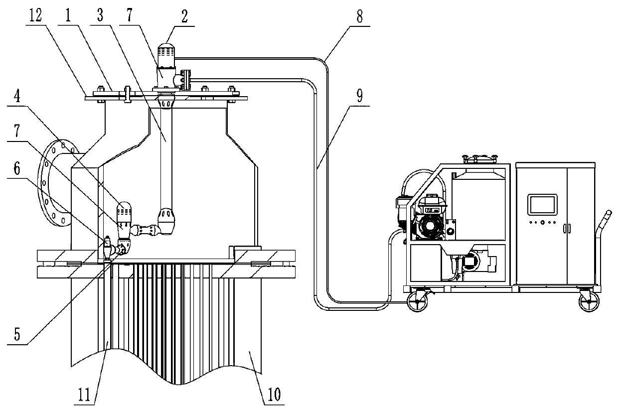
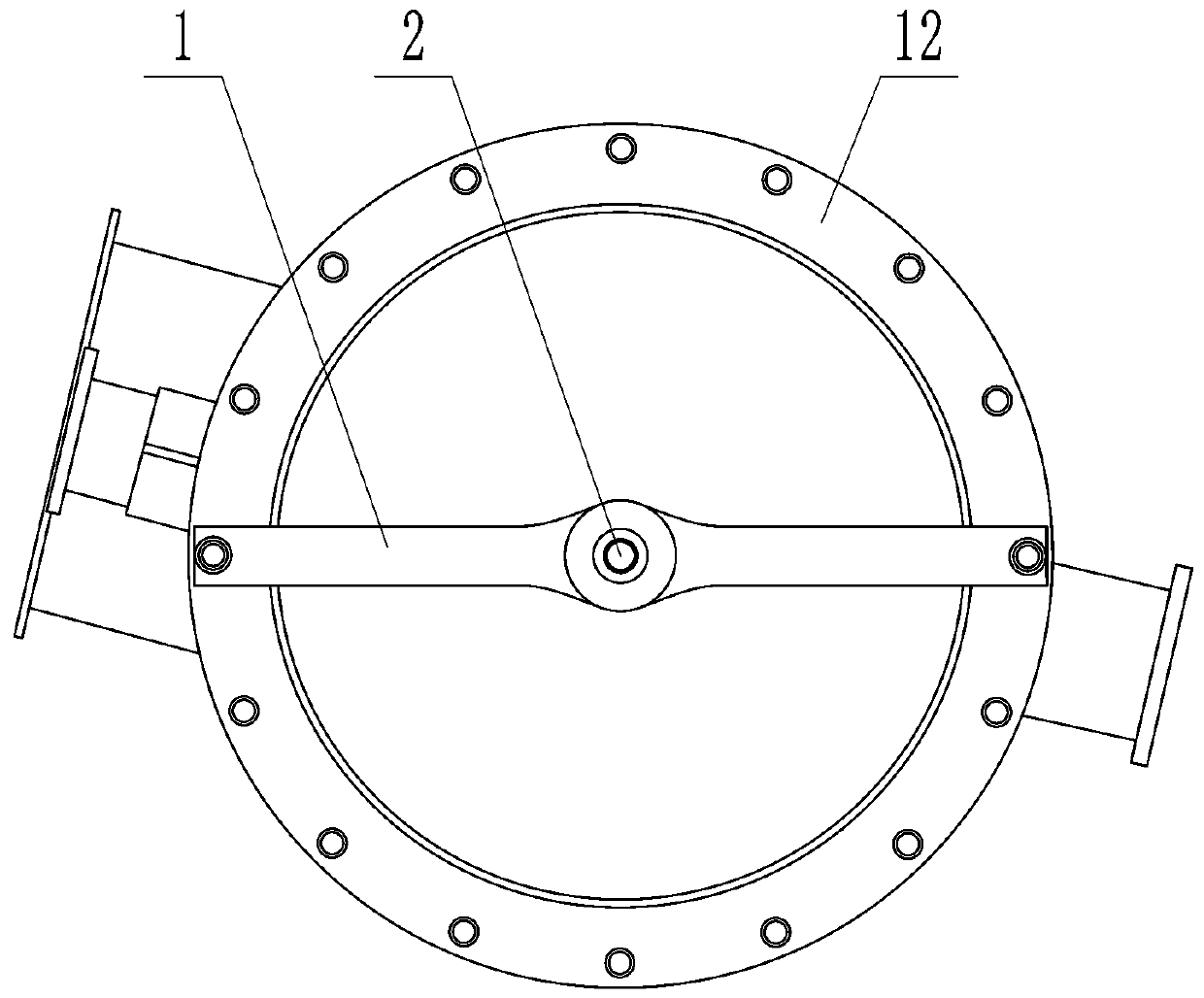
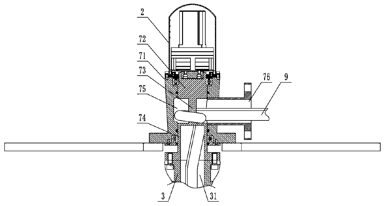
[0030] Such as Figure 1-4 As shown, a high-pressure water cleaning robot device includes a first driving motor 2, a first rotating mechanical arm 3, a second driving motor 4, a second rotating mechanical arm 5 and a spray mechanism 6; the first driving motor 2 passes through A rotary joint 7 drives the rotation of the first rotary mechanical arm 3, the second drive motor 4 is installed at the driving end of the first rotary mechanical arm 3, and the second drive motor 4 drives the second rotary mechanical arm 3 The arm 5 rotates, and the injection mechanism 6 is installed on the driving end of the second rotating mechanical arm 5; the first driving motor 2 and the first rotating mechanical arm 3 form a primary driving mechanism, and the second driving motor 4 and the second rotating mechanical arm The mechanical arm 5 forms a secondary ...


PUM


Abstract

The invention provides a high-pressure washing robot device. The high-pressure washing robot device comprises a multistage drive mechanism and a spraying mechanism, wherein a front-stage drive mechanism comprises a first drive motor and a first rotary mechanical arm, the first drive motor drives the first rotary mechanical arm to rotate through a rotary joint, a circuit channel is arranged insidethe first rotary mechanical arm, a high-pressure hose which is used for connecting the spraying mechanism is arranged in the circuit channel, the rotary joint comprises a fixed outer ring and a rotaryinner core arranged inside the fixed outer ring, the rotary inner core comprises drive shaft connecting parts at the two ends, a mechanical arm connecting part and a winding central part on the middle part, a circuit inlet is formed in a position, which corresponds to a wire winding space, of the side wall of the fixed ring, a circuit through hole for enabling the wire winding space to communicate with the circuit channel is formed in the mechanical arm connecting part, and the high-pressure hose gets across a wire winding central shaft and then passes through from the circuit through hole. The high-pressure washing robot device has the advantages that the structure is novel, the hose is not liable to wear, the service life is long, and maintenance cost is low.

Description

technical field [0001] The invention relates to a heat exchanger cleaning device, in particular to a high-pressure water cleaning robot device. Background technique [0002] Condensers, heat exchangers, air coolers, etc. will generate dirt during operation, and long-term operation will also cause the diameter of the heat exchange tube to become smaller or even blocked, which will not only reduce the operating efficiency of the equipment, but also cause tube The pollution and aging of the network will cause the forced outage of equipment and economic losses. In addition, after the equipment is out of service, if it is not cleaned in time, the difficulty of cleaning and the cost of maintenance will be increased after the dirt dries up. Therefore, it is very important to provide online and offline cleaning. [0003] At present, the above-mentioned industrial heat exchangers often adopt the method of shutdown, disassembly and cleaning, manual cleaning or cleaning with chemical...

Claims


Application Information

Patent Timeline
IPC IPC(8): B08B9/032
CPCB08B9/0323
Inventor 姚杰新姬博文冯波樊登科冯关琴陈海山
Owner 郑州赛为机电设备有限公司
Learn More