
Suitcase brake mechanism

A technology of brake mechanism and luggage, which is applied in the field of luggage, can solve the problems of inflexibility and damage of brakes or loose brakes, and achieve the effect of flexible damage and not easy damage

Inactive Publication Date: 2019-04-26
HANGZHOU GEMA SUITCASES & BAGS
View PDF5 Cites 3 Cited by
  • Summary
  • Abstract
  • Description
  • Claims
  • Application Information

AI Technical Summary

Problems solved by technology

[0002] In the luggage industry, in order to prevent the suitcase from sliding due to inertia on the bus or subway, most of the suitcase wheels will be equipped with brakes, but the brakes on the suitcase wheels on the market are mainly foot-operated. This kind of brake is not only easy to be damaged due to the user's foot stepping, but also not flexible to operate the brake or loosen the brake with the foot.

Method used


Image

  • Suitcase brake mechanism
  • Suitcase brake mechanism
  • Suitcase brake mechanism

Examples


Embodiment 1

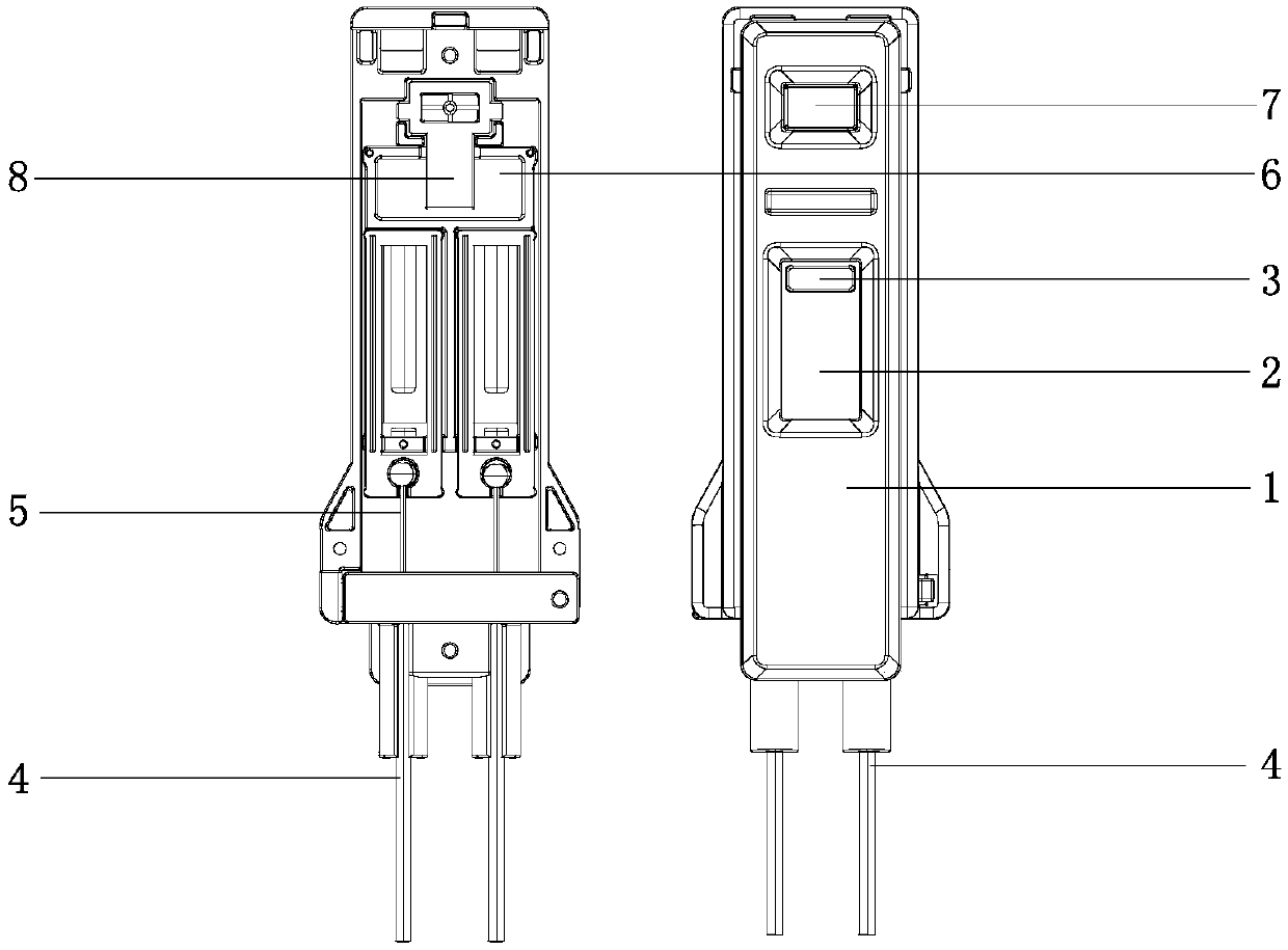
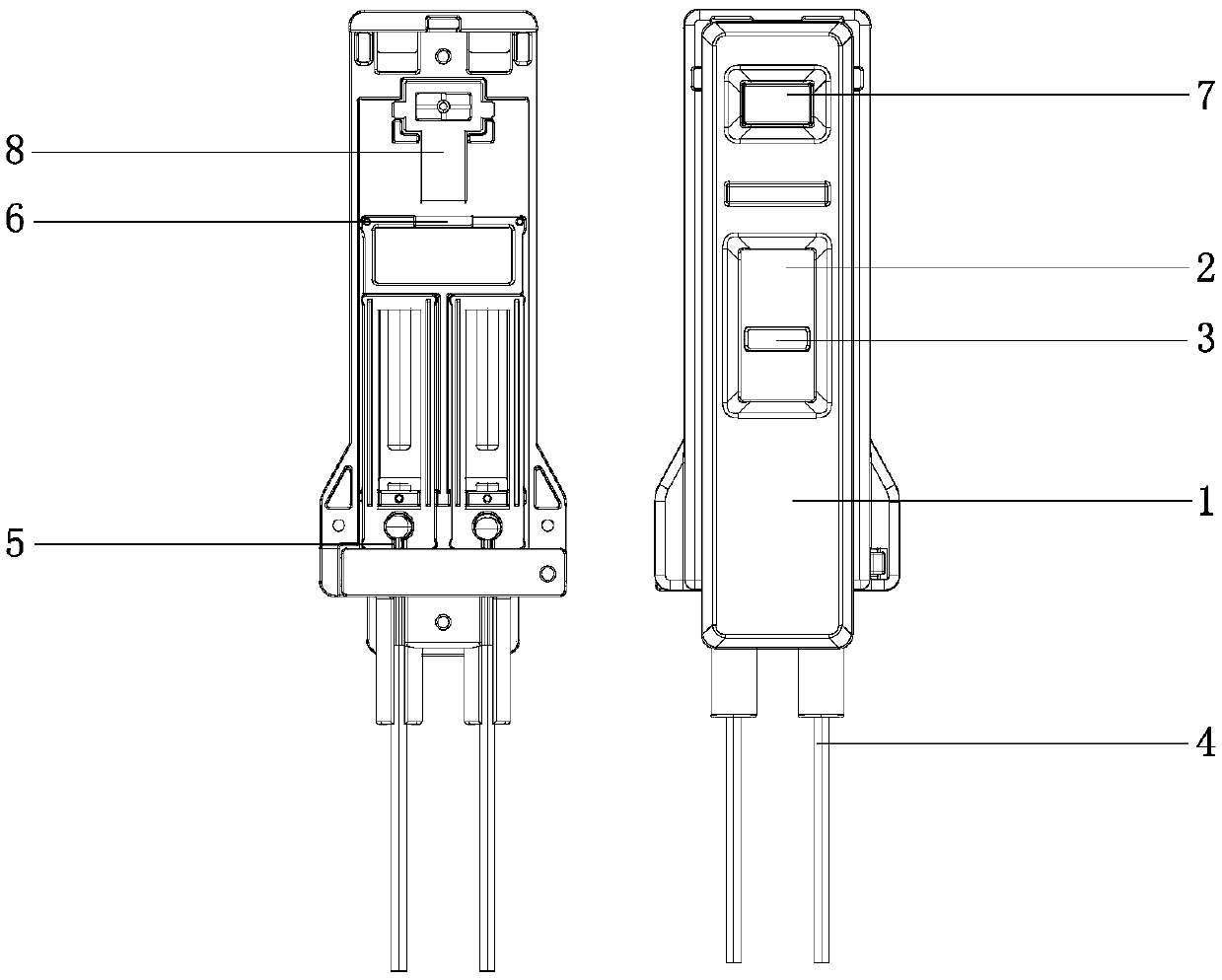
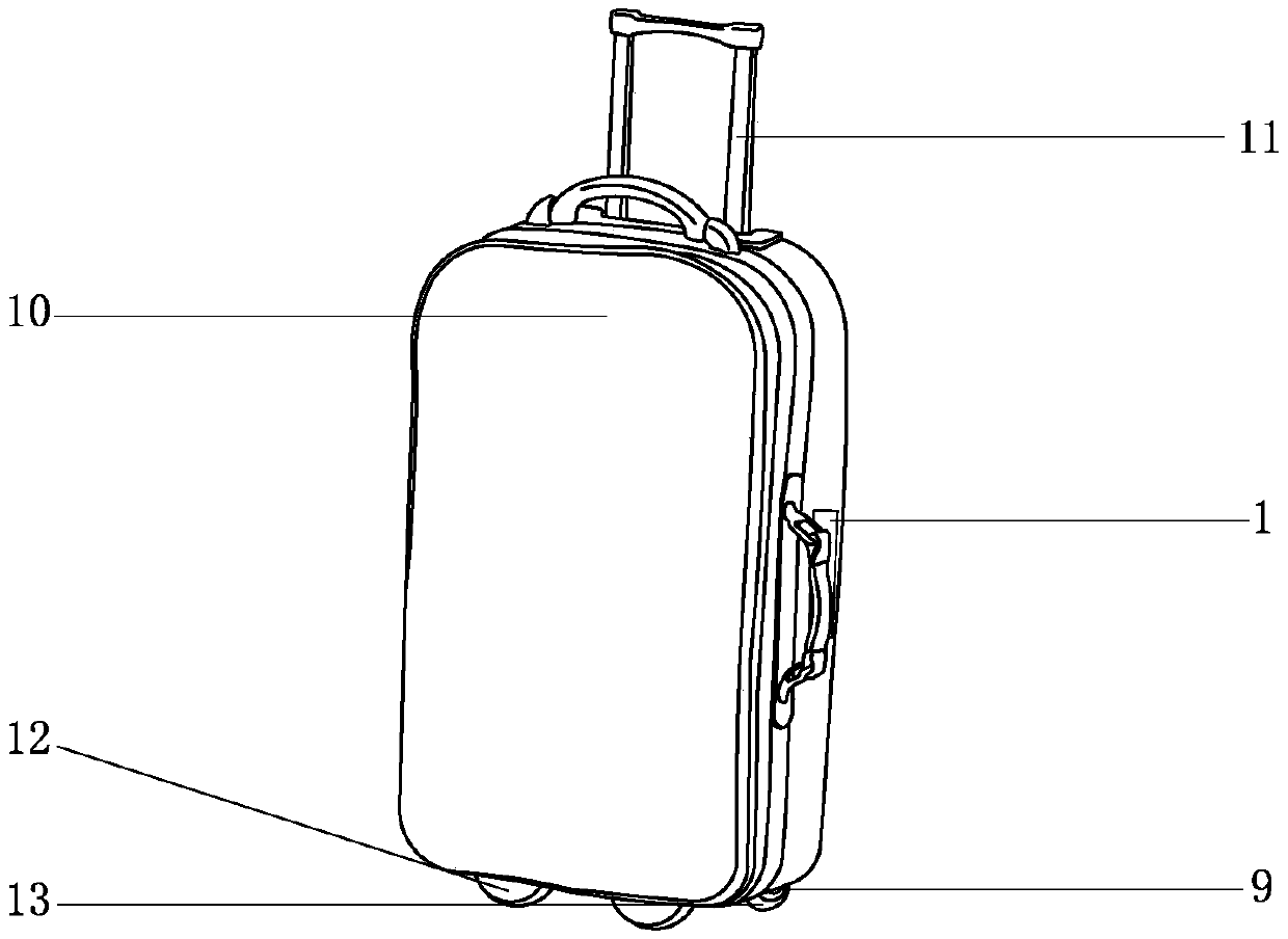
[0025] Such as Figure 1-3 A suitcase brake mechanism shown mainly includes a housing 1 that can be installed on one side of the suitcase 10 and a brake device 9 installed on the wheels of the suitcase 10, wherein a handbrake mechanism is arranged in the housing 1 , the handbrake mechanism is connected with the brake device 9. When the user needs to brake the luggage case 10, the brake device 9 can be driven only by operating the hand brake mechanism, so that the wheels of the luggage case 10 can be braked. Hand operation is convenient to realize the braking effect of the luggage case 10 .

[0026] In this example, combined with figure 1 To describe, the housing 1 can be divided into positive and negative sides, wherein figure 1 The left side of the middle is the reverse side, and the right side is the front side.

[0027] In this embodiment, the handbrake mechanism in the housing 1 mainly includes a handle 3 and a connecting piece 4, and an opening 2 matching the handle 3 ...

Embodiment 2

[0035] This embodiment differs from Embodiment 1 in that, in this embodiment, no return spring mechanism 5 is provided between the bottom of the handle 3 and the inner wall of the housing 1, and the return spring mechanism 5 is arranged on the brake. between the device 9 and the connecting piece 4, so that when the connecting piece 4 is lifted under the drive of the handle 3, the brake device 9 is in a braking state, and the return spring mechanism 5 between the two exerts a downward pulling force on the connecting piece 4, and when the The draw-in slot 6 of the handle 3 is separated from the locking mechanism 8, and the handle 3 and the connecting piece 4 will reset downward under the pulling force of the return spring mechanism 5, so that the braking device 9 releases the brake.

[0036] In this embodiment, the brake device 9 is specifically a disc brake.


PUM


Abstract

The invention discloses a suitcase brake mechanism, and relates to the field of bags and suitcases. The brake mechanism mainly comprises a shell which is arranged on one side of a suitcase and a brakedevice which is arranged on a suitcase wheel. The suitcase brake mechanism is characterized in that a hand brake mechanism connected with the brake device is arranged on the shell; the brake device is controlled by pulling the hand brake mechanism to realize brake, and the shell is arranged on one side of the suitcase; the hand brake mechanism arranged on the suitcase is in controlled connectionwith the brake, so that the hand brake mechanism can be operated conveniently by a user; when a user needs to brake a suitcase, the brake device can realize brake under driving of the hand brake mechanism as long as the hand brake mechanism is pulled, so that the aim of conveniently realizing braking a suitcase can be achieved.

Description

technical field [0001] The invention relates to the field of luggage, in particular to a luggage brake mechanism. Background technique [0002] In the luggage industry, in order to prevent the suitcase from sliding due to inertia on the bus or subway, most of the suitcase wheels will be equipped with brakes, but the brakes on the suitcase wheels on the market are mainly foot-operated. This kind of brake is not only prone to damage due to the user's foot stepping, but also inflexible to operate the brake or loosen the brake with the foot. Contents of the invention [0003] In order to solve the above-mentioned technical problems, the object of the present invention is to provide a trunk brake mechanism that can be operated by hand to conveniently brake the trunk. [0004] In order to achieve the above object, the technical solution adopted by the present invention is: a luggage brake mechanism, which mainly includes a housing arranged on one side of the luggage and a braki...

Claims


Application Information

Patent Timeline
IPC IPC(8): A45C5/14
CPCA45C5/145
Inventor 吕舒旖
Owner HANGZHOU GEMA SUITCASES & BAGS
Learn More