Novel fan junction box
A junction box and fan technology, which is applied in the field of transformers, can solve the problems that the terminals cannot be effectively protected, the opening at the bottom of the box enters the junction box, and the opening of the base is not tightly sealed, so as to reduce the risk of water ingress, The effect of light weight and simple structure
- Summary
- Abstract
- Description
- Claims
- Application Information
AI Technical Summary
Problems solved by technology
Method used
Image


Examples
Embodiment 1
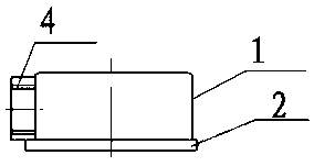
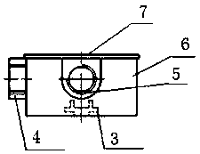
[0032] A new fan junction box, at least including a cover plate 7 and a box body 6, the box body 6 is a square box, the side wall of the box body 6 is provided with an outlet 4 and an inlet 5 for connecting cables, the box The inside of the body 6 is fixedly connected to the terminal 3 by screws, and the cables of the wire outlet 4 and the wire inlet 5 are connected to the terminal 3 respectively, and the cover plate 7 is sealed and fixedly connected to the box body 6 by screws.
[0033] The cable wires are divided into power wires and motor lead wires, the wire outlet 4 is connected to an external power wire, and the wire inlet 5 is connected to the motor lead wires. The present invention sets the wire outlet 4 and the wire inlet 5, avoiding the need for the motor lead wire to enter the junction box from the opening at the bottom of the junction box, and there is a risk of water ingress due to poor sealing of the opening of the base.
[0034] The connection terminal of the pr...
Embodiment 2
[0036] On the basis of Example 1, such as image 3 and Figure 4 As shown, the wire outlet 4 is arranged on the left side of the box body 6, the wire inlet 5 is arranged in front of the box body 6, and the wire outlet 4 and the wire inlet 5 are at 90 degrees; the wire outlet 4 and the wire inlet 5 have the same structure, Their outer ends all stretch out box body 6 to form boss, and the bottom of boss is semicircle, and top is plane, and through hole is arranged in the middle, and internal thread is arranged in through hole.
[0037] The four corners of the end face of the box body 6 are respectively provided with a cover plate installation screw hole 10, and the cover plate installation screw hole 10 is a blind hole; the cover plate 7 is provided with 4 cover plate installation holes 8, 4 The cover mounting holes 8 correspond to the four cover mounting screw holes 10, and the cover mounting holes 8 are through holes. The bottom of the box body 6 is a plane.
Embodiment 3
[0039] On the basis of Embodiment 1 or 2, the cable outlet 4 and the cable inlet 5 are threadedly connected with a waterproof cable lock for locking the cables. Waterproof cable lock head is prior art, belongs to the well-known technology of those skilled in the art. Available in the market and online.
[0040] Such as Figure 4 , Figure 5 and Figure 6 As shown, the cover plate 7 is a square, and arc-shaped grooves are arranged on the four corners of the upper surface of the cover plate, and the four cover plate installation holes 8 are respectively arranged in the four arc-shaped grooves; The surface is provided with protrusions along the periphery, and a cover plate gasket 9 is arranged inside the protrusions; as Figure 7As shown, the cover plate gasket 9 is square-shaped, and holes corresponding to the cover plate mounting holes 8 are provided on its four corners.
[0041] The middle position of the bottom in the box body 6 is provided with a cross-shaped mounting s...
PUM
 Abstract
Description
Claims
Application Information
 - R&D
- Intellectual Property
- Life Sciences
- Materials
- Tech Scout
- Unparalleled Data Quality
- Higher Quality Content
- 60% Fewer Hallucinations
Browse by: Latest US Patents, China's latest patents, Technical Efficacy Thesaurus, Application Domain, Technology Topic, Popular Technical Reports.
© 2025 PatSnap. All rights reserved.Legal|Privacy policy|Modern Slavery Act Transparency Statement|Sitemap|About US| Contact US: help@patsnap.com