
Welding structure for annular-wave metal corrugated pipe, and production method thereof

A metal bellows, welded structure technology, applied in metal processing equipment, non-detachable pipe connections, pipes/pipe joints/pipe fittings, etc., can solve the problem of cracking caused by bending stress, unreliable weld quality, and waste of corrugated materials. and other problems, to achieve the effect of saving stainless steel materials, improving the reliability of welding and sealing, and reducing the stress on the welding seam

Active Publication Date: 2019-04-19
孙铭阳
View PDF6 Cites 1 Cited by
  • Summary
  • Abstract
  • Description
  • Claims
  • Application Information

AI Technical Summary

Problems solved by technology

This production method has the following deficiencies: first, the welding efficiency is low; second, the quality of the weld seam is unreliable; third, the weld seam is prone to cracking due to the bending stress caused by the extension of the corrugated waves;
The application of bellows has developed rapidly in the past 20 years, but the corrugated connection method has always been limited to wave crest flattened welded structures with poor stress

Method used


Image

  • Welding structure for annular-wave metal corrugated pipe, and production method thereof
  • Welding structure for annular-wave metal corrugated pipe, and production method thereof
  • Welding structure for annular-wave metal corrugated pipe, and production method thereof

Examples


Embodiment 1

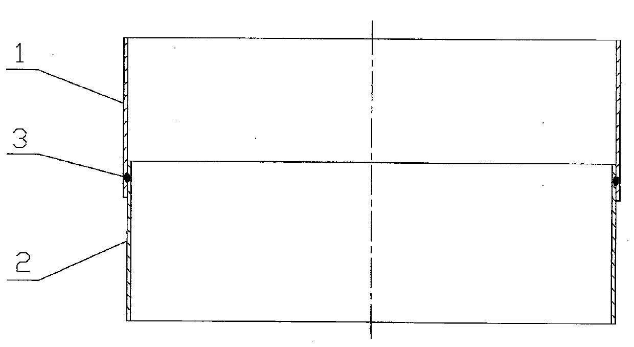
[0026] A manufacturing method of ring-wave metal bellows. The number of pipe blanks to be connected is determined according to the total number of corrugations actually required. First, the stainless steel coil is unrolled and blanked according to the circumference of the pipe blanks, and welded to form corrugated pipes. Tube blank A1 and tube blank B2 or more tube blanks. When determining the blanking size of the circumference of the tube blank, let the adjacent tube blanks meet the requirements of tight socket. Then two or more tube blanks are nested end to end at adjacent ends and partially overlapped (that is, overlapped), such as figure 1 , the amount of lap overlap can meet the forming and welding requirements. Then use a seam welding machine (also known as a seam welding machine) with a disc electrode to perform seam welding at the overlap to form a weld 3. The welding current and welding speed are adjusted to the welding point that the weldment is fully fused and the ...

Embodiment 2

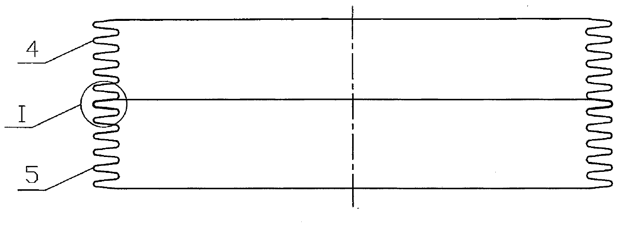
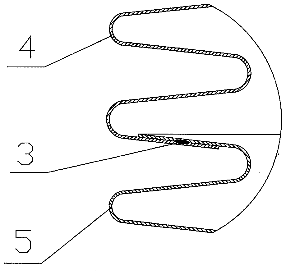
[0028] Such as Figure 4 As shown, the overlapping seam welding seam 3 is set in the crest area of ​​the corrugation during forming, and the rest is the same as the first embodiment.

Embodiment 3

[0030] Such as Figure 5 As shown, the seam welding seam 3 at the overlap is set in the trough area of ​​the corrugation during forming, and the rest is the same as the first embodiment.


PUM


Abstract

The invention relates to a welding structure for connecting an annular-wave metal corrugated pipe, and a production method. The welding structure is characterized in that a circumferential welding seam is formed in the sidewall of corrugation, and a simple and reliable lap seam welding structure is adopted. The production method comprises the following steps: superposing a plurality of pipe blanksused for producing the corrugated pipe on an end part and carrying out seam welding along a circumference to form a welding seam of lap seam welding at first; and then forming the needed corrugationthrough an expansion method, and forming the welding seam in the sidewall of the corrugation during formation. According to the scheme, a traditional process is changed; bending stress born by the welding seam is low; simple welding, high efficiency, high welding seam quality and beautiful appearance are achieved; and meanwhile, a stainless steel material can be saved.

Description

technical field [0001] The invention relates to a welding structure of an annular wave metal bellows and a manufacturing method thereof, which belongs to the field of metal corrugation compensation, and is especially suitable for the manufacture of large-diameter thin-wall bellows of multiple tube blanks. Background technique [0002] Metal bellows are widely used in the fields of flexible connection of pipelines, displacement compensation and volume compensation. Thin-walled bellows with larger diameters are mostly annular corrugations with parallel corrugations (relative to spiral corrugations), and the connection is more difficult. Large-diameter metal bellows usually use stainless steel sheets to weld the tube blanks to form annular corrugations. Since the width of the stainless steel sheets is usually less than 1.2 meters, the corrugations that can be formed by a tube blank are limited. When the number of corrugations is large, usually Connect multi-section metal bellow...

Claims


Application Information

Patent Timeline
IPC IPC(8): F16L13/02F16L27/10F16L27/11B21C37/08B21C37/30B23K33/00
CPCB21C37/0807B21C37/30B23K33/006F16L13/02F16L27/1017F16L27/11
Inventor 吴祥勤王金帅郭思聪孙铭阳
Owner 孙铭阳
Learn More