
Relative rotating type writing brush holder and hair cleaning device and use method thereof

A technology of relative rotation and cleaning device, which is applied in the direction of removing and removing the pen tip, printing, writing utensils, etc., which can solve the problems of loss, occupied space, difficult placement, and large water demand of buckets, so as to facilitate large-scale popularization and application, Good cleaning effect, ingenious and reasonable structure

Inactive Publication Date: 2019-04-19
潘艾欣
View PDF5 Cites 6 Cited by
  • Summary
  • Abstract
  • Description
  • Claims
  • Application Information

AI Technical Summary

Problems solved by technology

However, the brush cleaning tool commonly used by people at present is not very convenient, especially when going out to sketch, the bucket used for cleaning needs a lot of water, which wastes water resources; it takes up space and is not easy to place, easy to knock over, the user needs to spend time cleaning, and even stains wet painting, causing damage

Method used


Image

  • Relative rotating type writing brush holder and hair cleaning device and use method thereof
  • Relative rotating type writing brush holder and hair cleaning device and use method thereof

Examples


Embodiment 1

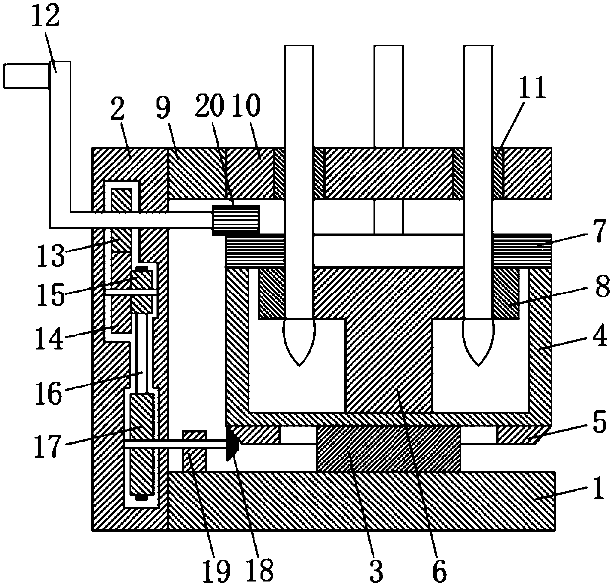
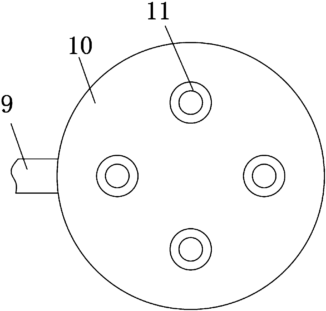
[0025] See figure 1 with figure 2 , A relatively rotating brush barrel cleaning device, comprising: a frame, a cleaning tank 4 arranged on the frame rotating, a barrel cleaning mechanism arranged on the cleaning tank 4 directly or indirectly rotating, and a mechanism that drives the barrel cleaning mechanism to rotate The first transmission mechanism, the second transmission mechanism that drives the rotation of the cleaning tank 4, and the driving mechanism for driving the first transmission mechanism and the second transmission mechanism to operate synchronously, the first transmission mechanism is directly or indirectly arranged on the cleaning tank 4, The second transmission mechanism is directly or indirectly arranged on the frame, and the driving mechanism is rotatably arranged on the frame.

[0026] The first transmission mechanism includes a gear plate 7 and a transmission gear 20. The gear plate 7 is rotatably arranged on the upper surface of the cleaning tank 4, the tr...

Embodiment 2

[0043] In this embodiment, the second transmission mechanism includes a bevel gear, a bevel gear plate and at least two gears that mesh with each other. In the case of two gears, one gear is fixedly connected to the driving mechanism, and the other gear is fixedly connected to the bevel gear coaxially, the bevel gear meshes with the bevel gear plate, and the bevel gear plate is fixedly connected to the bottom of the cleaning tank 4. In the case of three gears, the upper end of the intermediate gear meshes with the first gear, the lower end meshes with the third gear, the first gear is fixedly connected to the drive mechanism, the third gear is coaxially fixedly connected to the bevel gear, and the bevel gear meshes with the bevel gear plate , The bevel gear plate is fixedly connected to the bottom of the cleaning tank 4. The other structures and principles are the same as those in Embodiment 1, and will not be repeated.


PUM


Abstract

The invention discloses a relative rotating type writing brush holder and hair cleaning device and a use method thereof. The cleaning device comprises a rack, a cleaning pond rotatably arranged on therack, a brush holder cleaning mechanism directly or indirectly rotatably arranged on the cleaning pond, a first transmission mechanism for driving the brush holder cleaning mechanism to rotate, a second transmission mechanism for driving the cleaning pond to rotate and a driving mechanism for driving the first transmission mechanism and the second transmission mechanism to synchronously operate,the first transmission mechanism is directly or indirectly arranged on the cleaning pond, the second transmission mechanism is directly or indirectly arranged on the rack, and the driving mechanism isrotatably arranged on the rack. A brush holder and brush hair of a writing brush can be synchronously cleaned efficiently and portably, the two transmission mechanisms synchronously operate under theeffect of one driving mechanism, and the device is ingenious and convenient.

Description

Technical field [0001] The invention relates to the technical field of brush cleaning tools, in particular to a relatively rotating type brush barrel and whisker cleaning device and a method of use thereof. Background technique [0002] The brush is a kind of art supplies commonly used by people for painting. It is light and convenient when used, can make the brush strokes plump and powerful, and provide people with great visual enjoyment. However, the commonly used brush cleaning tools are not very convenient, especially when going out for sketching. The cleaning bucket requires a lot of water and wastes water resources; it takes up space and is not easy to place, easy to knock over, and users need to spend time to clean up, even if it touches Wet paintings cause losses. Summary of the invention [0003] In view of the above problems, the present invention provides a relatively rotating type brush barrel and whisker cleaning device and its use method. The structure is ingenious ...

Claims


Application Information

Patent Timeline
Patent Type & Authority Applications(China)
IPC IPC(8): B43K13/02
CPCB43K13/02
Inventor 潘艾欣
Owner 潘艾欣
Learn More