
Buffer device for welding wire, welding system and welding robot

A buffer device, welding device technology, applied in welding equipment, welding accessories, arc welding equipment and other directions, can solve the problems of increasing the weight burden of welding workers, unfavorable storage and arrangement, and unfavorable manual welding, etc., to improve economic practicability , Shorten the production cycle and reduce the effect of wire blocking

Pending Publication Date: 2019-04-19
HANGZHOU KAIERDA ROBOT TECH CO LTD
View PDF1 Cites 2 Cited by
  • Summary
  • Abstract
  • Description
  • Claims
  • Application Information

AI Technical Summary

Problems solved by technology

Due to the need for the welding core to bend and deform in the guide hose, the guide hose needs a thicker diameter, which directly leads to the large volume and weight of the guide hose and even the buffer device used for the welding wire
The buffer device for welding wire can be applied to the automatic welding system, and can also be applied to manual work; the buffer device for welding wire is bulky and heavy, which is not conducive to accurate positioning in the automatic welding process, especially not conducive to long-term manual work. Welding will increase the weight burden of welders, quickly consume workers' physical energy, and even affect the quality of welding
In addition, the large-diameter guide hose is not conducive to the storage and organization of the welding machine system or wire feeding device when moving

Method used


Image

  • Buffer device for welding wire, welding system and welding robot
  • Buffer device for welding wire, welding system and welding robot
  • Buffer device for welding wire, welding system and welding robot

Examples


Embodiment 1

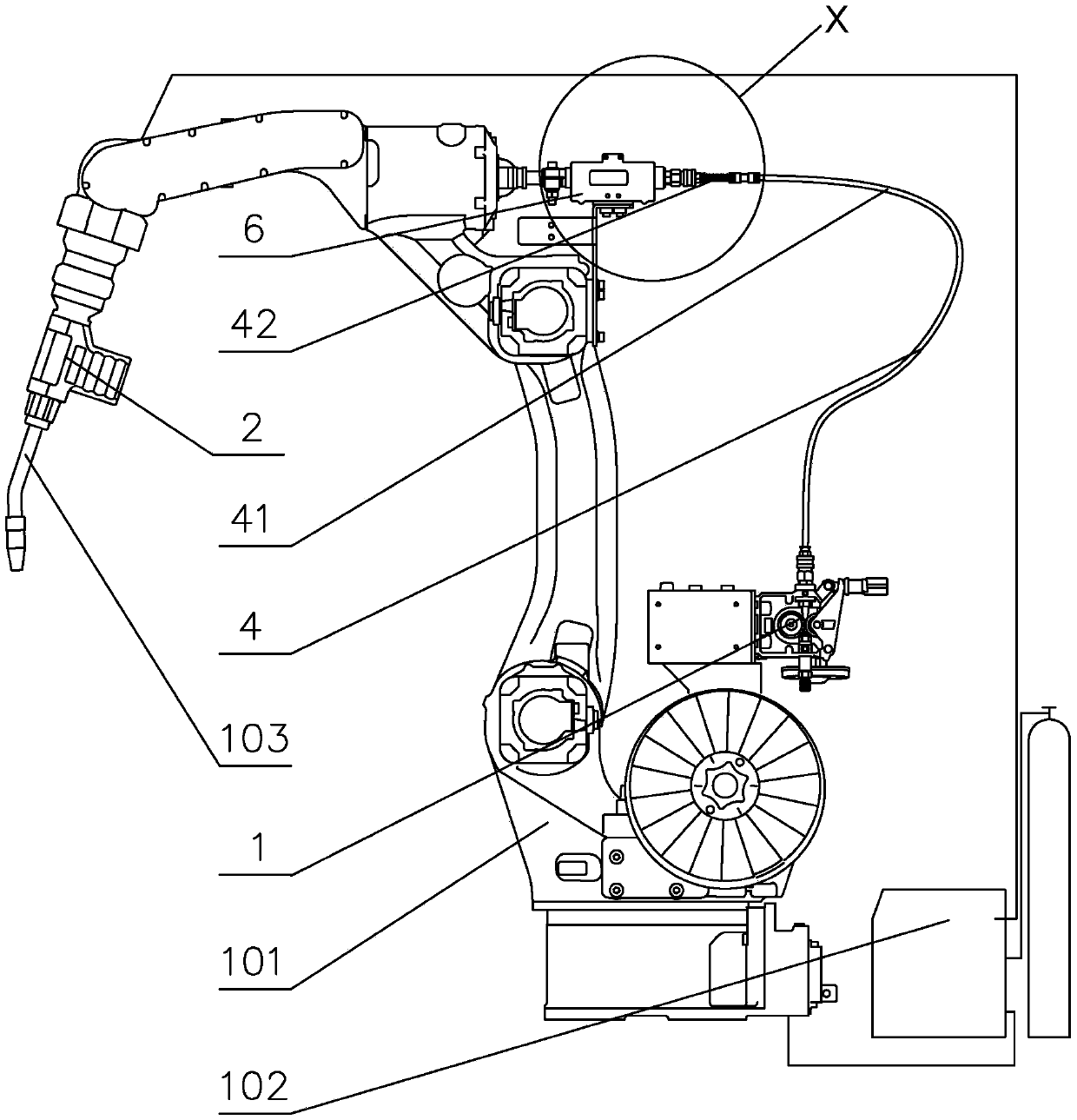
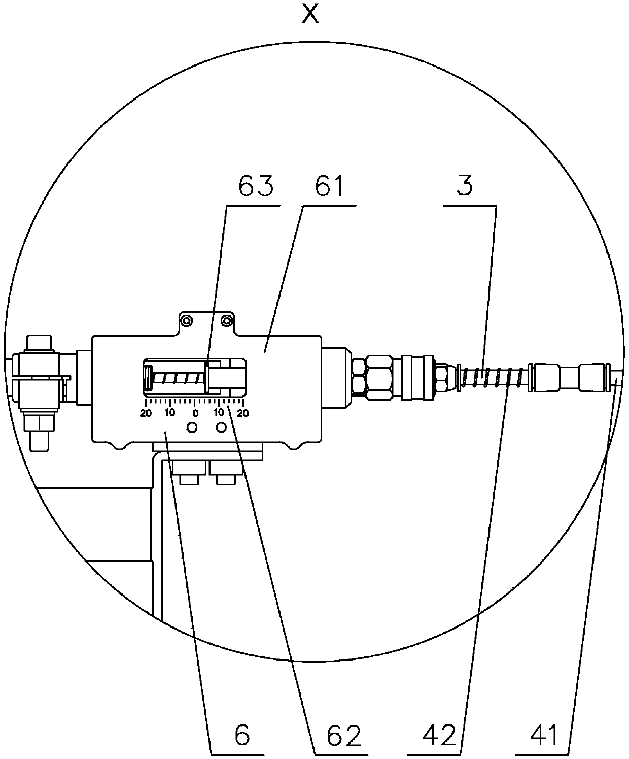
[0045] figure 1 It is a structural schematic diagram of a welding robot applying a buffer device for welding wire in an embodiment of the present invention. Such as figure 1 As shown, the welding robot includes a welding robot 101 , a welding power source 102 , a welding torch 103 , a first wire feeding unit 1 , a second wire feeding unit 2 , a wire feeding inner tube 3 , a wire feeding sleeve 4 , and an indicating unit 6 . The welding torch 103 is arranged at the end of the welding robot body 101 ; the welding torch 103 , the first wire feeding part 1 and the second wire feeding part 2 are respectively electrically connected to the welding power source 102 . The indicating part 6 is arranged between the first wire feeding part 1 and the second wire feeding part 2 on the side close to the second wire feeding part 2, the indicating part 6 is fixed on the welding device, the wire feeding inner tube 3, the wire feeding sleeve The tube 4 is provided between the first wire feedin...

Embodiment 2

[0073] The structure of embodiment 2 is the same as that of embodiment 1, the main difference is that both ends of the wire feeding sleeve hose 41 in embodiment 2 are respectively fixed to the wire feeding inner tube 3, and the wire feeding inner tube 3 cannot be placed on the wire feeding sleeve hose. 41 to increase the length, it can only move in the elastic tube 42, the gap between the wire feeding sleeve 4 and the wire feeding inner tube 3 in embodiment 1 is small enough, so that the wire feeding inner tube 3 is inside the wire feeding sleeve 4 Can only move axially.

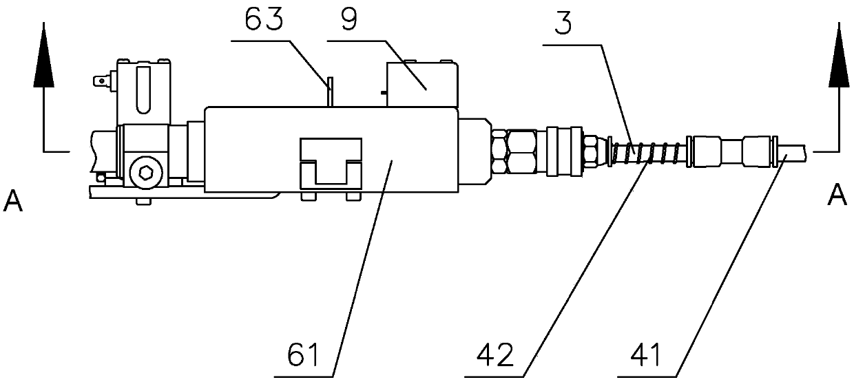
[0074] Such as Figure 1 to Figure 4 As shown, the wire feeding sleeve hose 41 and the wire feeding inner tube 3 are fixed on the first wire feeding part 1, and the wire feeding inner tube 3 sequentially passes through the wire feeding sleeve hose 41 and the elastic tube 42 and extends into the indicating part 6, Both ends of the wire feeding sleeve flexible pipe 41 are fixed with the wire feeding inner tub...

Embodiment 3

[0076] The structure of embodiment 3 is consistent with that of embodiment 1, the main difference is that the length direction of the wire feeding sleeve 4 in embodiment 3 is an axially retractable elastic tube 42, and the wire feeding sleeve 4 in embodiment 1 includes The axially stretchable elastic tube 42 and the axially incompressible or very small guide hose 41 are compressed.

[0077] Since the elastic tube 42 determines the maximum buffering capacity of the welding wire, in order to achieve the largest possible buffering capacity of the welding wire, the wire feeding sleeve 4 is used as the elastic tube 42 whose length direction is axially expandable. In addition, the use of elastic tube 42 for the whole wire feeding sleeve 4 can reduce the parts used for the whole device of the buffer device for welding wire, reduce the management requirements of parts, reduce the assembly process and related process requirements in the device manufacturing process, and reduce managemen...


PUM


Abstract

The invention provides a buffer device for a welding wire. The buffer device for the welding wire is arranged between a first wire feeding part and a second wire feeding part, and one end of a wire feeding inner pipe is fixedly connected with a welding device body; the other end of the wire feeding inner pipe can axially move; a feeding sleeve is arranged at the outer part of the wire feeding inner pipe in a sleeving manner; and at least a part of the feeding sleeve is an axial telescopic elastic pipe. According to the buffer device, a buffer space is provided for the welding wire, the situation that the welding wire is blocked as the curvature of a wire feeding pipe is large due to relatively large welding wire back pulling quantity is reduced, the diameter of a protection pipe is relatively small, mass of the wire feeding pipe is reduced, gravity of the welding wire and inner and outer protection pipes is further reduced, friction force between the welding wire and the inner and outer protection pipes is further reduced, and precision of the welding wire buffer device is improved. According to a welding robot adopting the welding wire buffer device and a welding system thereof, the structure of welding equipment is simplified, besides, manufacturing cost is reduced, the production cycle is shortened, and economic practicability of the welding robot and the welding system thereof is improved.

Description

technical field [0001] The invention relates to a device for welding, in particular to a buffer device for welding wire. Background technique [0002] With the development of welding technology, especially with the development of welding automation, gas metal arc welding with high welding efficiency and good weld quality has been more and more widely used. Since the short-circuit transition used in gas metal arc welding has the disadvantages of large welding spatter, relevant personnel have found that two wire feeders, one in front and one in the back, can be used to synchronously drive the welding wire to advance and retreat periodically, thereby promoting the welding wire machine. Sexual short circuit to achieve welding working status in less spatter mode. Due to the mismatch of the two wire feeders, the response of the wire feeding system is slow during the welding process, which affects the efficiency of the welding operation and the quality of the weld. There is there...

Claims


Application Information

Patent Timeline
IPC IPC(8): B23K9/133B23K9/32B23K9/173
CPCB23K9/133B23K9/173B23K9/32
Inventor 侯润石吴勇健田成昱王胜华魏秀权朱科隆
Owner HANGZHOU KAIERDA ROBOT TECH CO LTD
Learn More