
An infusion cart with a telescopic infusion stand

A technology of infusion stand and infusion cart, which is applied in the field of medical equipment, can solve the problems of high cost, large size, and difficulty in moving by medical staff, and achieve the effect of simple structure and easy operation

Inactive Publication Date: 2021-04-16
重庆市九龙坡区中医院
View PDF6 Cites 0 Cited by
  • Summary
  • Abstract
  • Description
  • Claims
  • Application Information

AI Technical Summary

Problems solved by technology

Row-mounted infusion stands have the advantages of smooth translation, flexible rotation, and stable expansion and contraction, but they are expensive and need to be modified; floor-standing infusion stands are generally not easy to move, and are very bulky, which is difficult for medical staff to move
[0004] Therefore, someone has proposed a modernized medical vehicle, but the existing medical infusion vehicle has a relatively simple structure. Although it can be used by multiple patients at the same time, in order to keep the balance of the vehicle, its hooks are generally at the same height. It needs to be adjusted to different heights; although there is an infusion cart with a retractable infusion rod type in the prior art, there is only one infusion rod on the infusion cart, and the infusion cart is in the process of moving, because the height of the infusion rod is relatively high. The balance of the whole car body is not good, it is easy to fall over, and the dumped infusion rod is easy to cause injury to people; considering the above problems comprehensively, it is necessary to optimize and upgrade the existing medical infusion car to meet the needs of use

Method used


Image

  • An infusion cart with a telescopic infusion stand
  • An infusion cart with a telescopic infusion stand
  • An infusion cart with a telescopic infusion stand

Examples


Embodiment 1

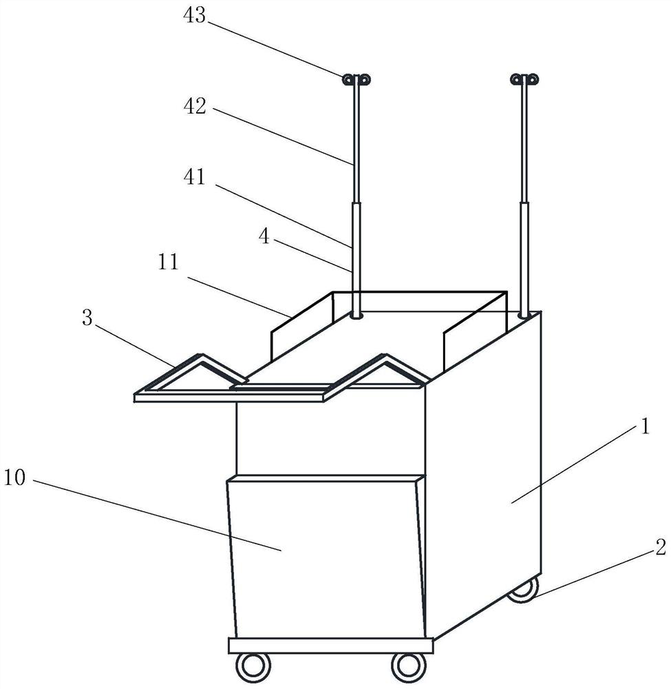
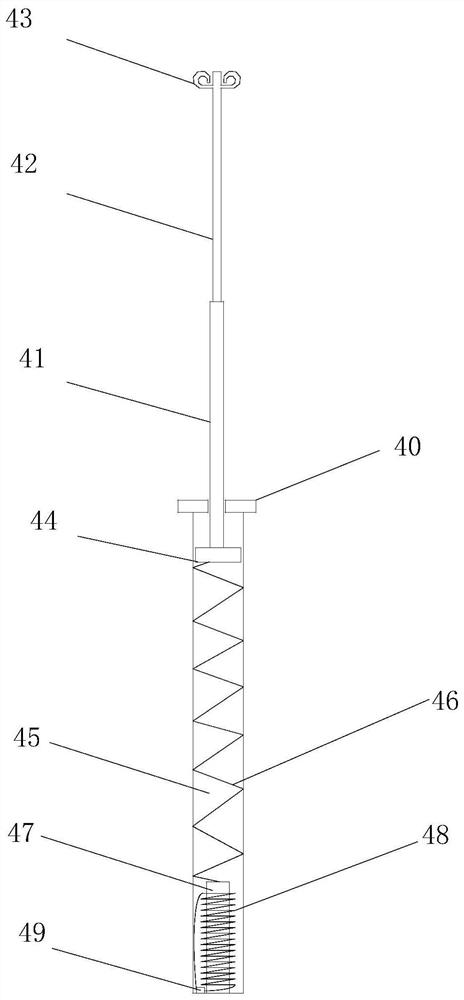
[0022] Such as figure 1 and figure 2 As shown, a kind of infusion vehicle with telescopic infusion stand of the present invention, the infusion vehicle with telescopic infusion stand comprises car body 1, wheel 2 and infusion stand 4; The bottom of described car body 1 is installed with four Wheel 2, one side of the top of the car body 1 is uniformly provided with a plurality of holes, and a ring magnet 40 is fixed above the hole; below each hole is a telescopic chamber 45, and a pressure spring 46 is installed in the telescopic chamber 45 , the other end of the pressure spring 46 is connected to the electromagnet core 47, and the electromagnet core 47 is fixed on the bottom of the telescopic cavity 45; a conductive coil 48 is wound around the periphery of the electromagnet core 47, and the two ends of the conductive coil 48 are correspondingly connected to the power supply box 49 positive and negative ends; the infusion stand 4 includes a first movable rod 41, a second mova...

Embodiment 2

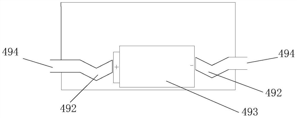
[0025] In this embodiment, on the basis of Embodiment 1, the power supply box 49 is further limited, as image 3 As shown, the left and right sides of the power supply box 49 are respectively provided with connection ports 494, and the two connection ports 494 correspond to the positive and negative poles of the power supply box 49 respectively; the outer side of the connection port 494 is connected to the conductive coil 48, and the inner side is connected to One end of the electric spring piece 492 ; the other end of the electric spring piece 492 is connected to the positive or negative pole of the battery 493 .

[0026] The electrified electromagnet core 47 and the magnet 44 repel each other. For example, the N pole of the electromagnet core 47 is opposite to the N pole of the magnet. The number of turns of the conductive coil 46 is 50-60 turns.

Embodiment 3

[0028] As an optional method, on the basis of Embodiment 2, in order to be more ergonomic and convenient for medical personnel to use, this embodiment is equipped with a push-pull handle 3 on the front side of the vehicle body 1, and a push-pull handle 3 is installed on the remaining sides. Connected horizontal railing 11 and longitudinal railing 11, an openable door 10 is provided in the front of the car body, through which medicine can be placed inside the car body; At the small hole, a switch is installed, which is connected to the battery in the power supply box, thereby artificially controlling the opening and closing of the battery.

[0029] Principle of use of the present invention:

[0030] When the infusion vehicle of the present invention is in a power-off state or in a dumped state, the electromagnet core is not connected to the battery, wherein, in the dumped state, the battery falls to the electric spring piece at one end, and the electric spring piece at the othe...


PUM


Abstract

The invention belongs to the technical field of medical devices, and specifically relates to an infusion vehicle with a retractable infusion stand. The infusion vehicle includes a vehicle body, wheels and an infusion stand; four wheels are installed at the bottom of the vehicle body, and one side of the top of the vehicle body is uniform There are multiple holes, and a ring magnet is fixed above the hole; under each hole is a telescopic cavity, and a pressure spring is installed in the telescopic cavity, and the other end of the pressure spring is connected to the electromagnet core, and the electromagnet core is fixed at the bottom of the telescopic cavity ; A conductive coil is wound around the periphery of the electromagnet core, and the two ends of the conductive coil are correspondingly connected to the positive and negative ends of the power supply box; the infusion stand includes a first movable rod, a second movable rod and an infusion hook; A second movable rod is connected, and an infusion hook is fixed above the second movable rod; a magnet is fixed below the first movable rod; and the magnet drives the infusion stand to move in the telescopic cavity. The invention can automatically shrink the infusion stand when the infusion cart is toppled over, so as to prevent the infusion stand from accidentally injuring people.

Description

technical field [0001] The invention belongs to the field of medical equipment and relates to clinical infusion equipment, in particular to an infusion vehicle with a retractable infusion stand. Background technique [0002] With the improvement of national living standards, the number of hospital patients has increased dramatically, resulting in chaotic scenes of overcrowded hospitals. The infusion is a large-dose injection that is injected into the human body by intravenous drip, usually contained in glass or plastic infusion bottles or infusion bags. middle. When in use, adjust the drip rate through the infusion set, and inject into the vein continuously and steadily to replenish body fluids, electrolytes or nutrients. [0003] At present, there are mainly two types of infusion stands used in clinical treatment: row-hanging infusion stands and floor-standing infusion stands. Row-mounted infusion poles have the advantages of smooth translation, flexible rotation, and sta...

Claims


Application Information

Patent Timeline
Patent Type & Authority Patents(China)
IPC IPC(8): A61M5/14
CPCA61M5/14A61M5/1415
Inventor 尹红梅彭支莲李素英李学英毛秀丽周敏王玉佳李晓琴
Owner 重庆市九龙坡区中医院
Learn More