Flexible optical-fiber ribbon

A technology of optical fiber ribbon and optical fiber, applied in the field of optical fiber ribbon, can solve the problems that non-planar optical fiber ribbon is not suitable for multi-channel fusion splicing operation, insufficient efficiency, etc.

Active Publication Date: 2019-04-16
PRYSMIAN SPA
View PDF17 Cites 4 Cited by
  • Summary
  • Abstract
  • Description
  • Claims
  • Application Information

AI Technical Summary

Problems solved by technology

Even so, the placement of planar fiber optic ribbons as stacks of rectangular or trapezoidal ribbons within circular tubes is not sufficiently space efficient
[0004] Mass-fusion ribbon splicing of optical fiber ribbons requires planar ribbon geometries, however, making non-planar optical fiber ribbons unsuitable for mass-fusion ribbon splicing operations

Method used


Image

  • Flexible optical-fiber ribbon
  • Flexible optical-fiber ribbon
  • Flexible optical-fiber ribbon

Examples


Embodiment Construction

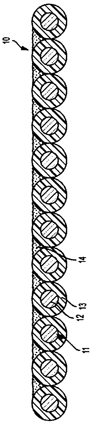
[0016] In one aspect, the invention includes flexible fiber optic ribbons that can be folded or crimped into a compact shape and then unfolded or unfolded into a planar configuration of parallel fibers without disrupting the ribbon structure or damaging the constituent fibers. In a substantially planar geometry, the flexible fiber optic ribbon facilitates multi-way fusion splicing. In substantially non-planar geometries, flexible fiber optic ribbons facilitate increased space efficiency within fiber optic cable structures such as micromodules or buffer tubes.

[0017] like Figure 1-4 As shown, the exemplary flexible fiber optic ribbons 10 each include a plurality of optical fibers 11 arranged side-by-side in such a manner that the optical fibers 11 are substantially parallel to each other. Individual optical fibers 11 comprising component glass fibers 12 and one or more surrounding coating layers 13 may be closely spaced or contiguous with adjacent optical fibers 11 , but ge...


PUM

PropertyMeasurementUnit
elongation at breakaaaaaaaaaa
thicknessaaaaaaaaaa

Abstract

The flexible optical-fiber ribbon can be reversibly adapted to both planar and non-planar shapes (e.g., packed via folding or rolling) without damaging the optical-fiber ribbon or its constituent optical fibers. This is achieved by bonding the plurality of optical fibres with a cured ribbon matrix (14) having elongation to break of at least 200% and a low Young's modulus of 1-20 MPa at 20 DEG C.

Description

technical field [0001] The present invention relates to optical fiber ribbons. Background technique [0002] Optical fibers offer advantages over conventional communication lines. Fiber optic communication networks can transmit significantly more information at significantly higher speeds than conventional wire-based networks. Accordingly, optical fibers are increasingly used in communication networks. An exemplary optical-fiber cable is disclosed in US Patent No. 5,682,454, which is incorporated herein by reference in its entirety. [0003] Optical fibers can be bonded together to form a planar fiber optic ribbon, which itself can be divided into subunits (eg, a twelve-fiber ribbon that can be split into 6 fiber subunits). A plurality of fiber optic ribbons may be aggregated to form ribbon stacks of various sizes and shapes, such as rectangular ribbon stacks or wherein the uppermost and / or lowermost fiber optic ribbons are aligned with the Those ribbons in the center ha...

Claims


Application Information

Patent Timeline
Patent Type & Authority Applications(China)
IPC IPC(8): G02B6/44
CPCG02B6/4403G02B6/4404G02B6/448
Inventor B·G·里施E·J·鲍曼
Owner PRYSMIAN SPA
Why Eureka
Try Eureka