Clamping device of AC contactor

A technology of AC contactors and locking devices, which is applied in the direction of relays, electromagnetic relays, and detailed information of electromagnetic relays. The installation is stable and reliable, and the effect of improving work efficiency

Active Publication Date: 2019-04-16
广东求精电气有限公司
View PDF9 Cites 5 Cited by
  • Summary
  • Abstract
  • Description
  • Claims
  • Application Information

AI Technical Summary

Problems solved by technology

[0002] The existing box clamping device is generally movable clamped on the guide rail, and the guide rail is provided in the cabinet, and the integrated device is clamped on the guide rail. However, this kind of card cannot be used in some specific positions. Connecting device, and the clipping device also has the situation that the clipping is not reliable
[0003] Due to the different on-site environments, sometimes it is necessary to use different types of AC contactors, and sometimes they need to be combined for joint use. Since there is no fixation between adjacent AC contactors, it is easy to Caused the AC contactor to slide or fall off, causing the AC contactor to deviate from its original position
In addition, it is easy to cause deformation of the wires of the AC contactor, and even cause the wires to fall off, and the adjacent AC contactors are not fixed, and the installation and removal are very cumbersome

Method used


Image

  • Clamping device of AC contactor
  • Clamping device of AC contactor
  • Clamping device of AC contactor

Examples


Embodiment Construction

[0024] The present invention will be further described below in combination with specific embodiments. Wherein, the accompanying drawings are only for illustrative purposes, showing only schematic diagrams, rather than physical drawings, and should not be construed as limitations on this patent; in order to better illustrate the embodiments of the present invention, some parts of the accompanying drawings will be omitted, Enlargement or reduction does not represent the size of the actual product; for those skilled in the art, it is understandable that certain known structures and their descriptions in the drawings may be omitted.

[0025] In the drawings of the embodiments of the present invention, the same or similar symbols correspond to the same or similar components; The orientation or positional relationship indicated by etc. is based on the orientation or positional relationship shown in the drawings, which is only for the convenience of describing the present invention ...


PUM


Abstract

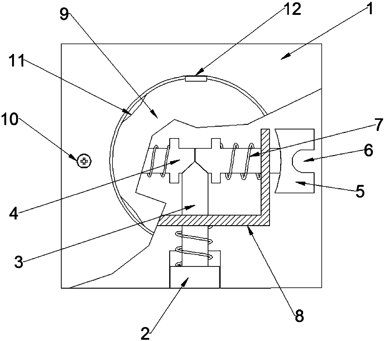
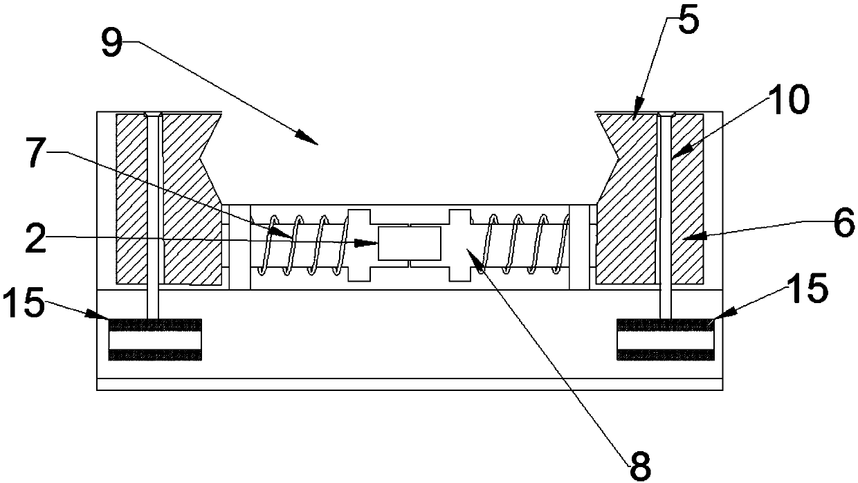
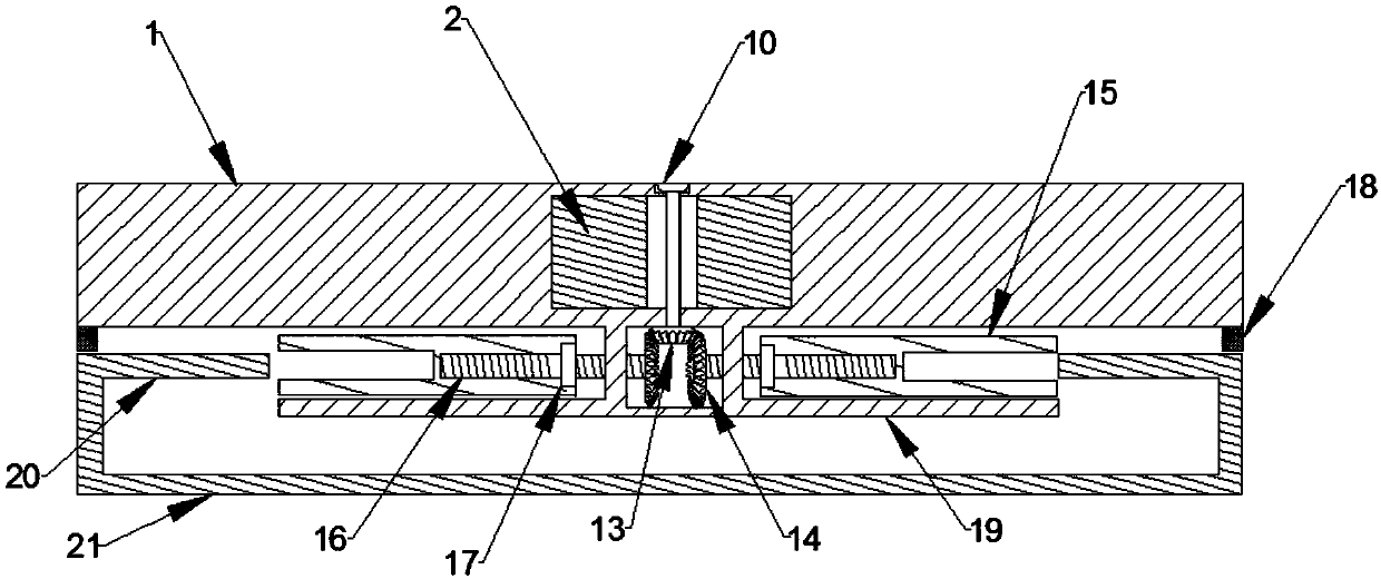
The invention provides a clamping device of an AC contactor, including a clamp body, a locking device and a guide rail. An under-voltage protector includes a control panel and a shell, and the shell is provided with a circular boss at the bottom thereof. The clamp body is provided with a first groove in the top surface thereof. A clamping mechanism is arranged on the clamp body. A locking device is arranged in the clamp body, and the locking device includes an unlocking button and a bilaterally symmetrical locking block. The locking block is provided with a slot. The circular boss is providedwith a bump. The slot in the locking block is matched with the bump on the circular boss. The circular boss of the AC contactor can be clamped into the slot. The circular boss of the AC contactor is inserted into the first groove and can be detachably clamped to the clamp body. A number of clamping elastic parts are evenly distributed in the first groove. The clamp body is detachably clamped to the guide rail. The clamping device of the invention is simple in structure, stable and reliable, and greatly saves time and improves the clamping efficiency.

Description

technical field [0001] The invention relates to the field of electrical equipment accessories, in particular to a clamping device for an AC contactor. Background technique [0002] The existing box clamping device is generally movable clamped on the guide rail, and the guide rail is provided in the cabinet, and the integrated device is clamped on the guide rail. However, this kind of card cannot be used in some specific positions. Connecting device, and the clamping device also has the situation that the clamping is not secure. [0003] Due to the different on-site environments, sometimes it is necessary to use different types of AC contactors, and sometimes they need to be combined for joint use. Since there is no fixation between adjacent AC contactors, it is easy to It caused the AC contactor to slide or fall off, causing the AC contactor to deviate from its original position. In addition, it is easy to cause deformation of the wires of the AC contactor, and even cause ...

Claims


Application Information

Patent Timeline
Patent Type & Authority Applications(China)
IPC IPC(8): H01H50/04
CPCH01H50/045H01H50/047H01H2050/049
Inventor 赵成雷陈正茂张传荣
Owner 广东求精电气有限公司
Why Eureka
Try Eureka