Capacity-regulating transformer with lightning protection function

A transformer and functional technology, applied in the direction of transformers, variable transformers, transformer/inductor components, etc., can solve the problems of increasing line loss and transformer loss, poor lightning protection effect, and harmonic voltage pollution of the power grid. The ability to withstand unbalanced loads, good lightning protection characteristics, and the effect of simple overall structure

Active Publication Date: 2019-04-16
ZHEJIANG BOTHWELL ELECTRIC
View PDF0 Cites 1 Cited by
  • Summary
  • Abstract
  • Description
  • Claims
  • Application Information

AI Technical Summary

Problems solved by technology

[0003] The lightning protection measures of the on-load capacity regulating transformer are mainly realized through the external lightning protection device. This kind of lightning protection device by destroying its own structure has high cost and poor lightning protection effect;
[0004] At present, the commonly used on-load capacity regulating transformer is a structure in which the high-voltage side winding is D-Y conversion and the low-voltage side winding is parallel-serial conversion, which makes its lightning protection structure particularly complicated. Moreover, this kind of capacity regulating transformer is Yyn0 connection, and as the power and quantity of single-phase electrical equipment increase, temporary power consumption, line faults, seasonal power consumption and other factors cause unbalanced distribution transformer three-phase load, Yyn0 connection will lead to The following problems: (1) Increase line loss and transformer loss; (2) Reduce transformer output; (3) Displacement of neutral point, phase voltage may rise to line voltage, and burn out electrical equipment; (4) Transformer outlet voltage Unbalanced, the three-phase voltage deviation at the user end is large, and the voltage quality cannot be guaranteed; (5) Harmonic voltage is generated to pollute the power grid

Method used


Image

  • Capacity-regulating transformer with lightning protection function
  • Capacity-regulating transformer with lightning protection function
  • Capacity-regulating transformer with lightning protection function

Examples


Embodiment Construction

[0042] In order to enable those skilled in the art to better understand the solutions of the present invention, the technical solutions in the embodiments of the present invention will be described clearly and completely below with reference to the accompanying drawings in the embodiments of the present invention.

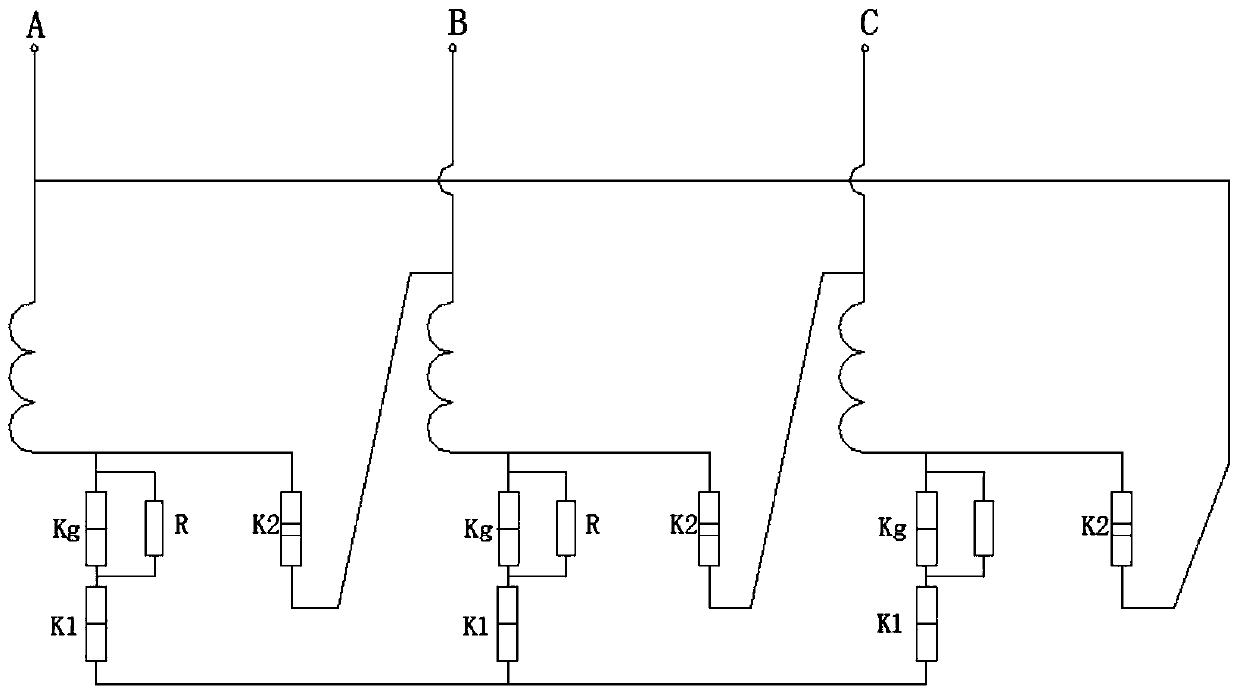
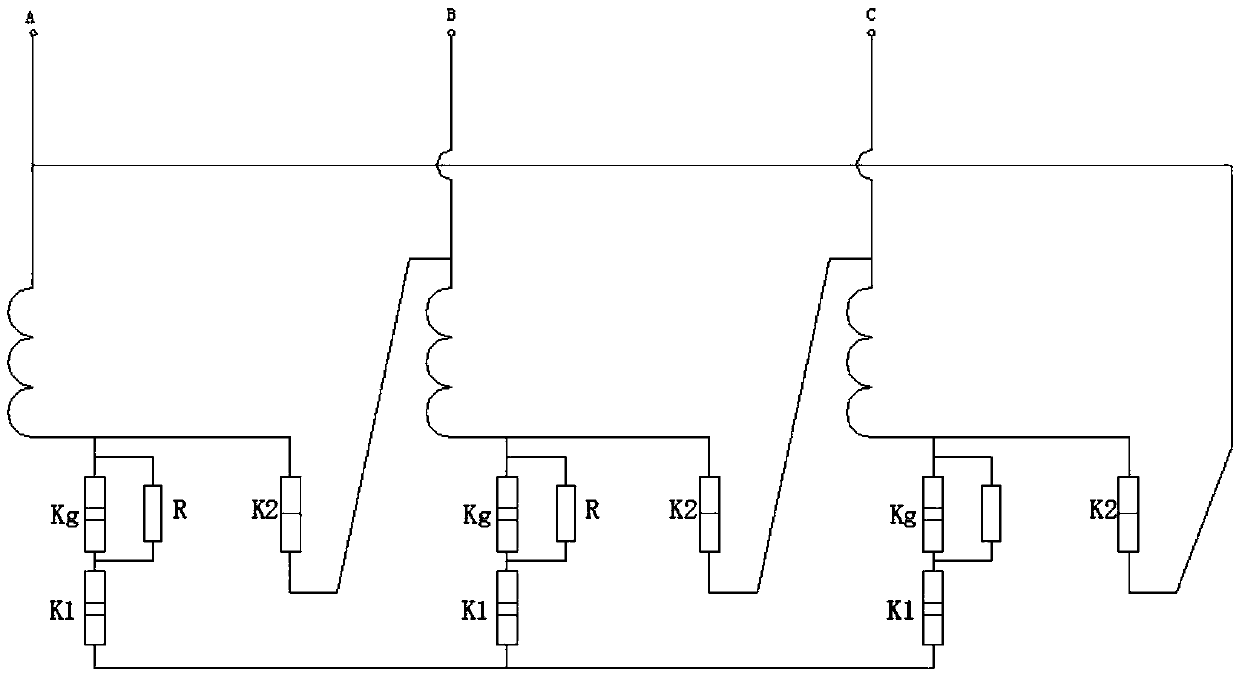
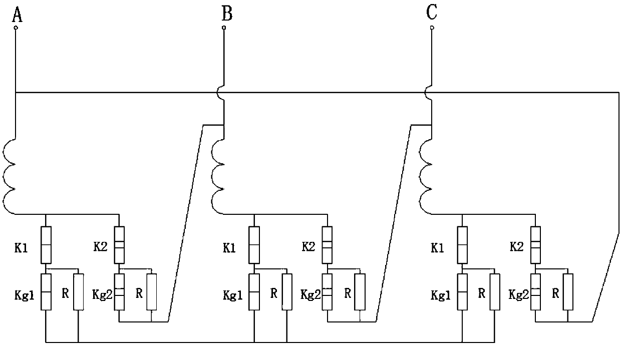
[0043] A capacity regulating transformer with lightning protection function, including three-phase high-voltage windings, three-phase low-voltage windings, on-load capacity regulating switches and other metal and non-metallic structural parts constituting the transformer. In the capacity state, the winding adopts the Dyn11 connection method; when switching to a small capacity, the winding adopts the Yzn11 connection method;

[0044] The low-voltage winding of each phase includes two coils with the same number of turns, and the two coils are wound on the iron core through an axially symmetrical distribution. Of course, in other embodiments, the two coils can also be ...


PUM


Abstract

The invention discloses a capacity-regulating transformer with the lightning protection function, which comprises a low-voltage winding and a high-voltage winding. When the capacity-regulating transformer is in a high-capacity state, the windings adopt the Dyn11 connection mode. When the transformer is switched to be in a low-capacity state, the windings adopt the Yzn11 connection mode. The capacity-regulating transformer is a special capacity-regulating transformer. When the capacity of the capacity-regulating transformer is switched to be small, the Yzn11 connection mode is achieved. The capacity of bearing unbalanced loads is high, that is, the capacity of bearing single-phase power supply is high. The capacity-regulating transformer is particularly suitable for places (such as rural areas and mountain areas) where three-phase loads are difficult to balance. The lightning protection performance of the transformer is good. The transformer is particularly suitable for being used as alightning protection transformer in a heavy-thunder region or a region with high soil resistivity.

Description

technical field [0001] The invention belongs to the technical field of transformer equipment in the power industry, and in particular relates to a capacity regulating transformer with a lightning protection function. Background technique [0002] The on-load capacity regulating transformer is a transformer with two rated capacities, large and small. According to the size of the load, the corresponding capacity regulating switch is used to switch the connection mode of the transformer windings without cutting off the power supply, and then realize the transformer between the two different capacities. switch between. [0003] The lightning protection measures of the on-load capacity regulating transformer are mainly realized by the external lightning protection device. This kind of lightning protection device by destroying its own structure has high cost and poor lightning protection effect; [0004] However, the commonly used on-load capacity-regulating transformer has a str...

Claims


Application Information

Patent Timeline
Patent Type & Authority Applications(China)
IPC IPC(8): H01F29/04H01F27/40H01F27/28
CPCH01F27/28H01F27/2828H01F27/306H01F27/40H01F27/402H01F29/00H01F29/04H01H33/666
Inventor 吴正文姜方军
Owner ZHEJIANG BOTHWELL ELECTRIC
Why Eureka
Try Eureka