
Virtual reality device and image correction method thereof

A virtual reality and image correction technology, applied in optics, instruments, character and pattern recognition, etc., can solve problems such as inconvenient wearing and experience for viewers, inability to provide three-dimensional information on the display screen, and easy to cause motion sickness. dizziness effect

Pending Publication Date: 2019-04-16
BOE TECH GRP CO LTD
View PDF8 Cites 3 Cited by
  • Summary
  • Abstract
  • Description
  • Claims
  • Application Information

AI Technical Summary

Problems solved by technology

One of the shortcomings of current virtual reality equipment is that the user is in a sealed visual environment after wearing the virtual reality equipment head-mounted display, but the two-dimensional display screen cannot give real three-dimensional information
What's more serious is that when viewing the display screen of a virtual reality device, the distance between the screen and the human eye is constant, so the focus remains unchanged, but different images will bring different "depth of field" information, however, this When the eye focus is not adjusted accordingly, when the balance of the visual system is broken, it will easily lead to dizziness, nausea, vomiting and other discomfort symptoms
This is also one of the reasons why most virtual reality devices are prone to motion sickness
[0003] For people with vision problems (such as myopia or hyperopia), they need to wear vision correction glasses before wearing virtual reality equipment, which brings a lot of inconvenience to the viewers in wearing and experience.

Method used


Image

  • Virtual reality device and image correction method thereof
  • Virtual reality device and image correction method thereof
  • Virtual reality device and image correction method thereof

Examples


Embodiment Construction

[0021] Reference will now be made in detail to the exemplary embodiments, examples of which are illustrated in the accompanying drawings. When the following description refers to the accompanying drawings, the same numerals in different drawings refer to the same or similar elements unless otherwise indicated. The implementations described in the following exemplary embodiments do not represent all implementations consistent with this application. Rather, they are merely examples of means consistent with aspects of the present application as recited in the appended claims.

[0022] The terminology used in this application is for the purpose of describing particular embodiments only, and is not intended to limit the application. Unless otherwise determined, the technical terms or scientific terms used in the present application shall have the ordinary meanings understood by those skilled in the art to which the present invention belongs. "First", "second" and similar words us...


PUM


Abstract

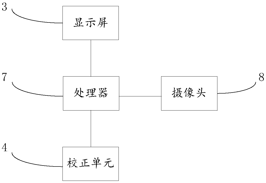
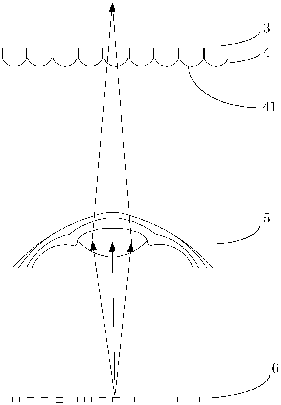
The application provides a virtual reality device and an image correction method thereof. The image correction method includes: acquiring a function relationship between an imaging light field of a display screen and an imaging light field of a human eye; acquiring an actual imaging light field of the human eye; calculating a corrected imaging light field of the display screen according to the function relationship and the actual imaging light field of the human eye; and rearranging pixels of the display screen to obtain a corrected imaging light field of the display screen. According to the application, the pixels of the virtual reality device are rearranged based on different visions and thus the imaging light field required by the displaying is obtained, so that adaptability of users with different eyesight is improved; and the user can watch the image directly without wearing the correcting glasses, so that the dizziness is avoided.

Description

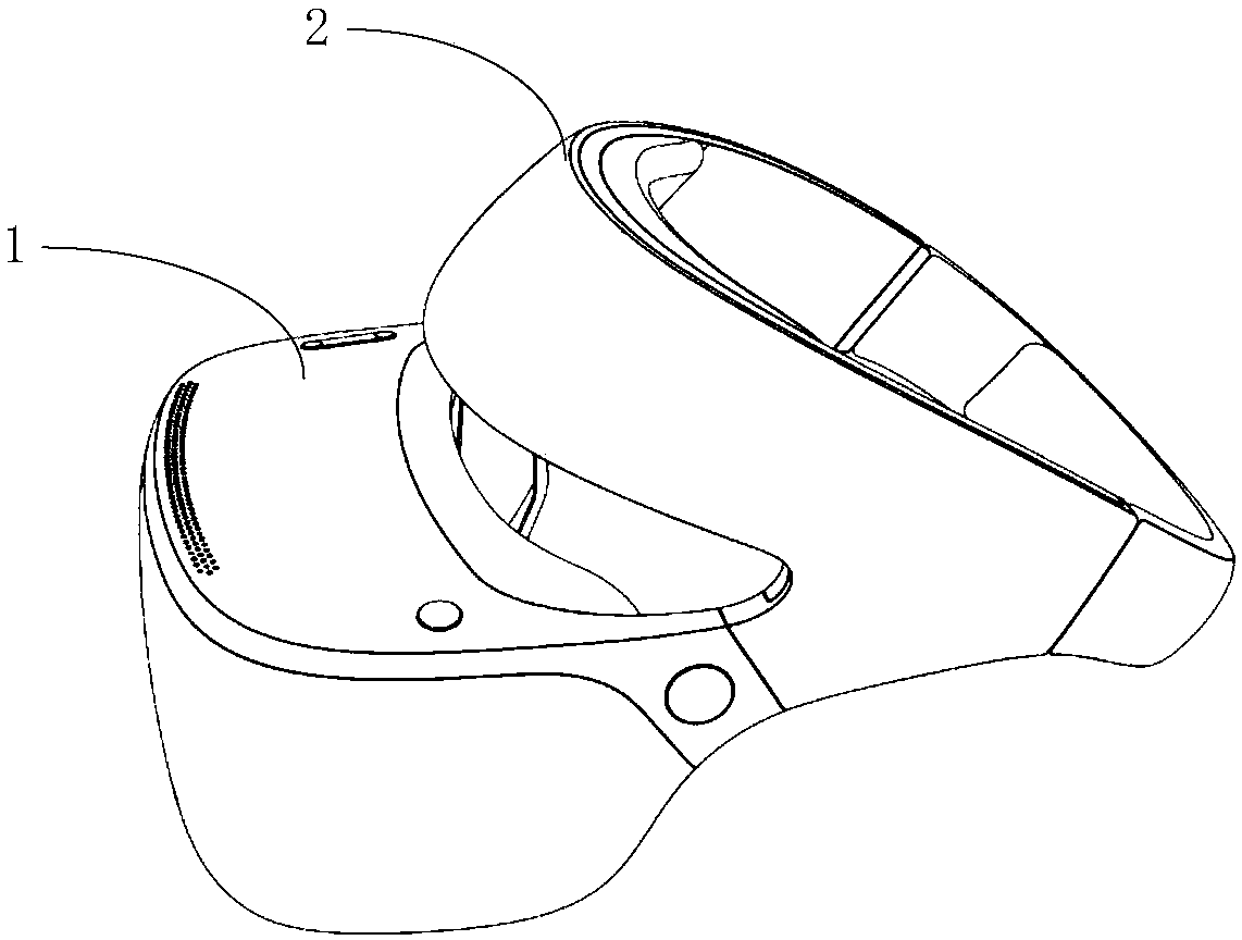
technical field [0001] The present application relates to the field of display technology, in particular to a virtual reality device and an image correction method thereof. Background technique [0002] With the rapid development of virtual reality technology, more and more users use virtual reality equipment for viewing movies, games, teaching or simulation and other fields. One of the disadvantages of current virtual reality equipment is that the user is in a sealed visual environment after wearing the virtual reality equipment head-mounted display, but the two-dimensional display screen cannot give real three-dimensional information. What's more serious is that when viewing the display screen of a virtual reality device, the distance between the screen and the human eye is constant, so the focus remains unchanged, but different images will bring different "depth of field" information, however, this When the eye focus is not adjusted accordingly, when the balance of the v...

Claims


Application Information

Patent Timeline
Patent Type & Authority Applications(China)
IPC IPC(8): G02B27/01G02B27/00G06K9/00
CPCG02B27/0018G02B27/0101G02B2027/0129G02B2027/014G06V40/18
Inventor 孙雪菲柳在健王新星
Owner BOE TECH GRP CO LTD
Learn More