Electronic yarn tension meter for textiles

A yarn tension, electronic technology, applied in tension measurement, application of stable tension/pressure testing material strength, instruments, etc., can solve the problem of inability to meet large-scale product testing, product quality and qualification rate reduction, single function, etc. problem, to achieve the effect of convenient card installation of water spray pipes, increased use effect, and strong flexibility

Inactive Publication Date: 2019-04-16
LINZHOU GUANGYUAN NEW MATERIAL TECH
View PDF12 Cites 5 Cited by
  • Summary
  • Abstract
  • Description
  • Claims
  • Application Information

AI Technical Summary

Problems solved by technology

[0002] As a process parameter in textile manufacturing and chemical fiber industrial production, yarn tension plays a very important role. In several spinning processes, such as drafting, twisting, and winding, it is necessary to measure and measure the yarn tension Control, in the yarn production process, if the tension of the yarn is not well controlled, it will cause the yarn to relax, the quality and pass rate of the product will be reduced, which is not conducive to the smooth progress of the follow-up work, so people usually Yarn tension measurement with electronic yarn tension meter
However, the electronic yarn tensiometers in the prior art cannot meet large-scale product testing, and the existing electronic yarn tensiometers can only be used to measure tension and have a single function

Method used


Image

  • Electronic yarn tension meter for textiles
  • Electronic yarn tension meter for textiles
  • Electronic yarn tension meter for textiles

Examples


Embodiment 1

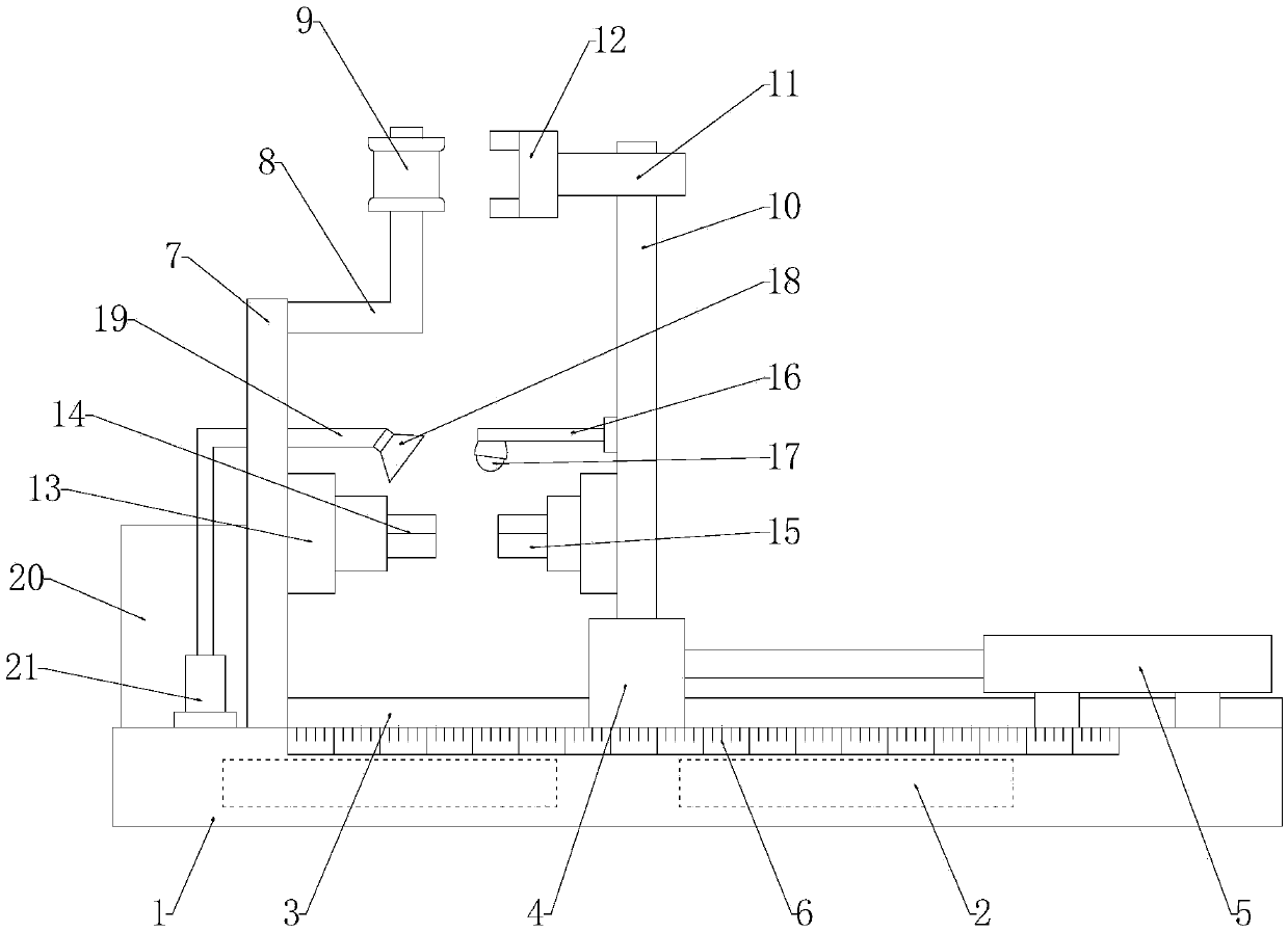
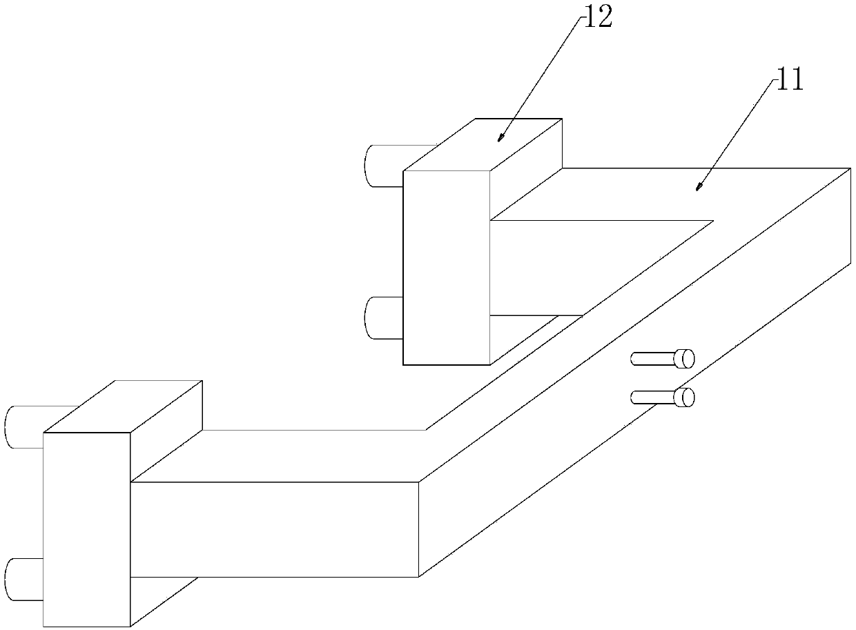
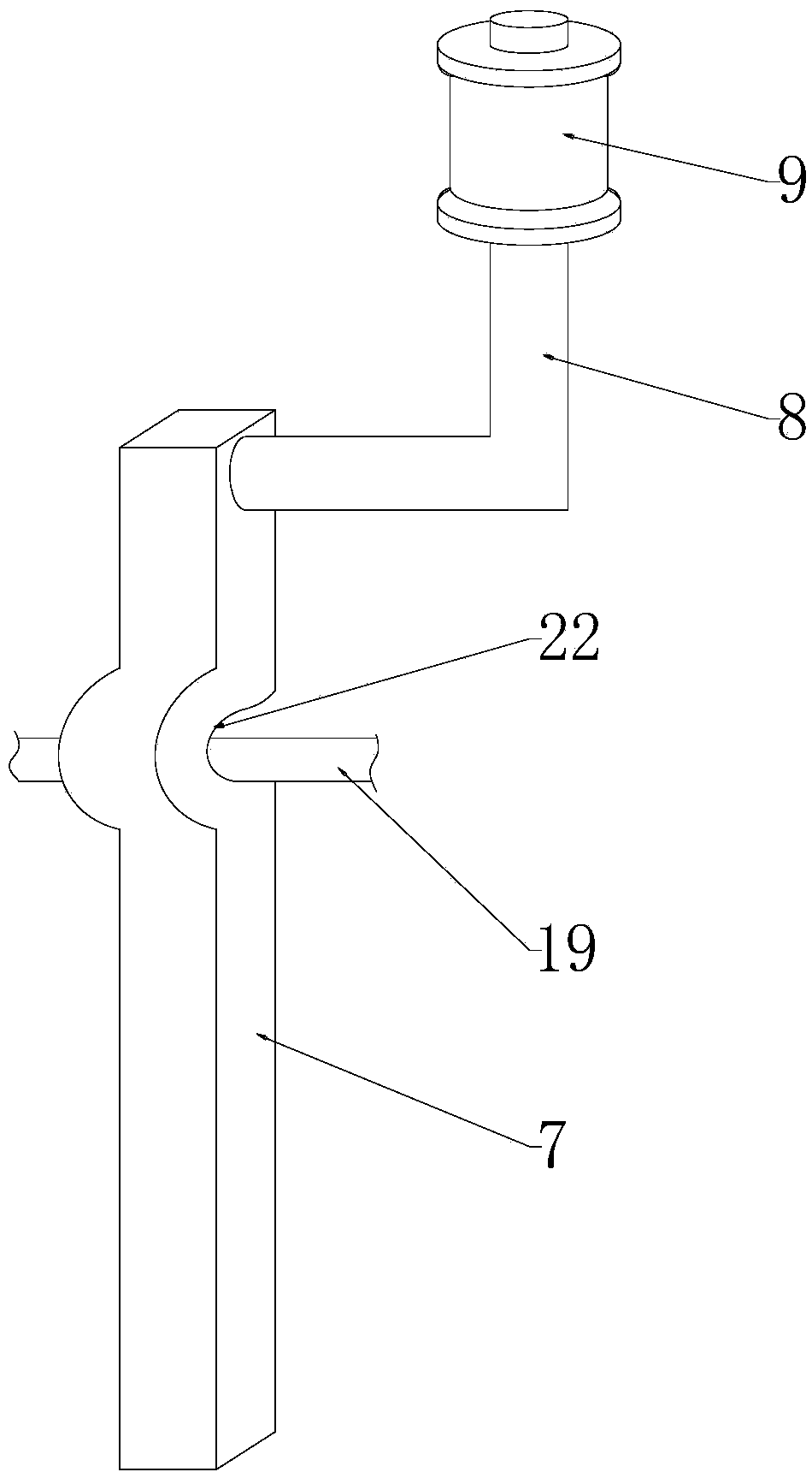
[0026] Such as Figure 1-3 As shown, an electronic yarn tension meter for weaving includes a base 1, a tension sensor 9 and a wire clamp 12, the tension sensor 9 and the wire clamp 12 are located at the same height on the base 1, and the tension sensor 9 is fixed on the L-shaped rod 8, The L-shaped rod 8 is welded on the top of the support column 7, and the support column 7 is fixed on the base 1 by bolts. The base 1 is provided with a battery 2 inside, and the battery 2 is connected to the grid through a charging wire. There are two clamps 12, and the two clamps 12 are respectively located on both sides of the tension sensor 9, and the two clamps 12 are fixed on the two ends of the movable U-shaped bar 11, and the U-shaped bar 11 is fixed on the top of the movable column 10 by bolts. The support column 7 is located below the tension sensor 9 and is provided with a fixed fixture 14. A force sensor 13 is provided between the fixed fixture 14 and the support column 7. The movabl...

Embodiment 2

[0030] Such as figure 1 As shown, the bottom of the movable column 10 is fixedly connected with the slider 4 by bolting or welding, the slider 4 is slidably installed on the guide rail 3, the guide rail 3 is integrally formed on the upper surface of the base 1 along the length direction of the base 1, and the slider 4 One end away from the support column 7 is fixed on the end of the telescopic rod of the cylinder 5 by screws, and the cylinder 5 is fixed on the end of the base 1 away from the support column 7 by a mounting block, and the telescopic rod of the cylinder 5 is parallel to the guide rail 3, and the cylinder 5 has control buttons.

[0031] By adopting the above technical solution, during the telescopic movement of the cylinder 5 , since the slider 4 is clamped on the guide rail 3 , it can guide the movement of the movable column 10 .

Embodiment 3

[0033] Such as figure 1 As shown, a nozzle 18 is arranged above the fixed fixture 14, and the nozzle 18 is installed at the end of the water spray pipe 19, and the water spray pipe 19 communicates with the water pump 21, and the water pump 21 is installed inside the water storage tank 20 through bolts, and the water storage tank 20 is fixed on the base 1, the water pump 21 is connected to the battery 2 through wires.

[0034] Such as Figure 4 As shown, an infrared heating lamp 17 is arranged above the movable fixture 15, and the infrared heating lamp 17 is installed at the end of the fixed rod 16, and the other end of the fixed rod 16 is welded to both ends of the fixed plate 23, and the fixed plate 23 is vertically fixed on the movable column 10 by bolts , The movable column 10 is provided with a control switch of an infrared heating lamp 17, and the infrared heating lamp 17 is connected with the storage battery 2 through a wire.

[0035] Such as image 3 As shown, the su...


PUM


Abstract

The invention discloses an electronic yarn tension meter for textiles. The electronic yarn tension meter for textiles comprises a base, a tension sensor and wire clamps; the tension sensor and the wire clamps are located at the same height on the base; the tension sensor is fixed onto an L-shaped rod; the L-shaped rod is welded onto the top of a supporting column; the supporting column is fixed onto the base through bolts; a storage battery is arranged inside the base; the storage battery is connected with a power grid through a charging wire; the wire clamps are movably mounted on the base; two wire clamps are provided; the two wire clamps are fixed at two ends of a movable U-shaped rod; the U-shaped rod is fixed onto the top of a movable column through a bolt; the supporting column is provided with a fixed fixture under the tension sensor; a stress sensor is arranged between the fixed fixture and the supporting column; the movable column is provided with a movable fixture below the wire clamps; and a stress sensor is arranged between the movable fixture and the movable column. With the electronic yarn tension meter for textiles adopted, the detection of the tension of the yarns can be realized in a short time, and the tensile strength of the yarns under different environments can be also measured.

Description

technical field [0001] The invention relates to the technical field of textiles, in particular to an electronic yarn tension meter for textiles. Background technique [0002] As a process parameter in textile manufacturing and chemical fiber industrial production, yarn tension plays a very important role. In several spinning processes, such as drafting, twisting, and winding, it is necessary to measure and measure the yarn tension Control, in the yarn production process, if the tension of the yarn is not well controlled, it will cause the yarn to relax, the quality and pass rate of the product will be reduced, which is not conducive to the smooth progress of the follow-up work, so people usually Yarn tension is measured with an electronic yarn tension meter. However, the electronic yarn tensiometer in the prior art cannot meet large-scale product testing, and the existing electronic yarn tensiometer can only be used for measuring tension, and has a single function. Conten...

Claims


Application Information

Patent Timeline
Patent Type & Authority Applications(China)
IPC IPC(8): G01L5/04G01N3/10G01N3/02
CPCG01L5/04G01N3/02G01N3/10G01N2203/0017G01N2203/0044G01N2203/0226
Inventor 李志伟李伟
Owner LINZHOU GUANGYUAN NEW MATERIAL TECH
Why Eureka
Try Eureka