Split-type cone drill bit
A roller cone bit and split technology, which is applied to drill bits, drilling equipment, earth-moving drilling, etc., can solve the problems of high labor intensity of workers, high quality of roller cones, inconvenient replacement of roller cones, etc., and achieve convenient and fast installation and replacement. Guarantee the effect of integration and quick installation
- Summary
- Abstract
- Description
- Claims
- Application Information
AI Technical Summary
Problems solved by technology
Method used
Image

Examples
Embodiment 1
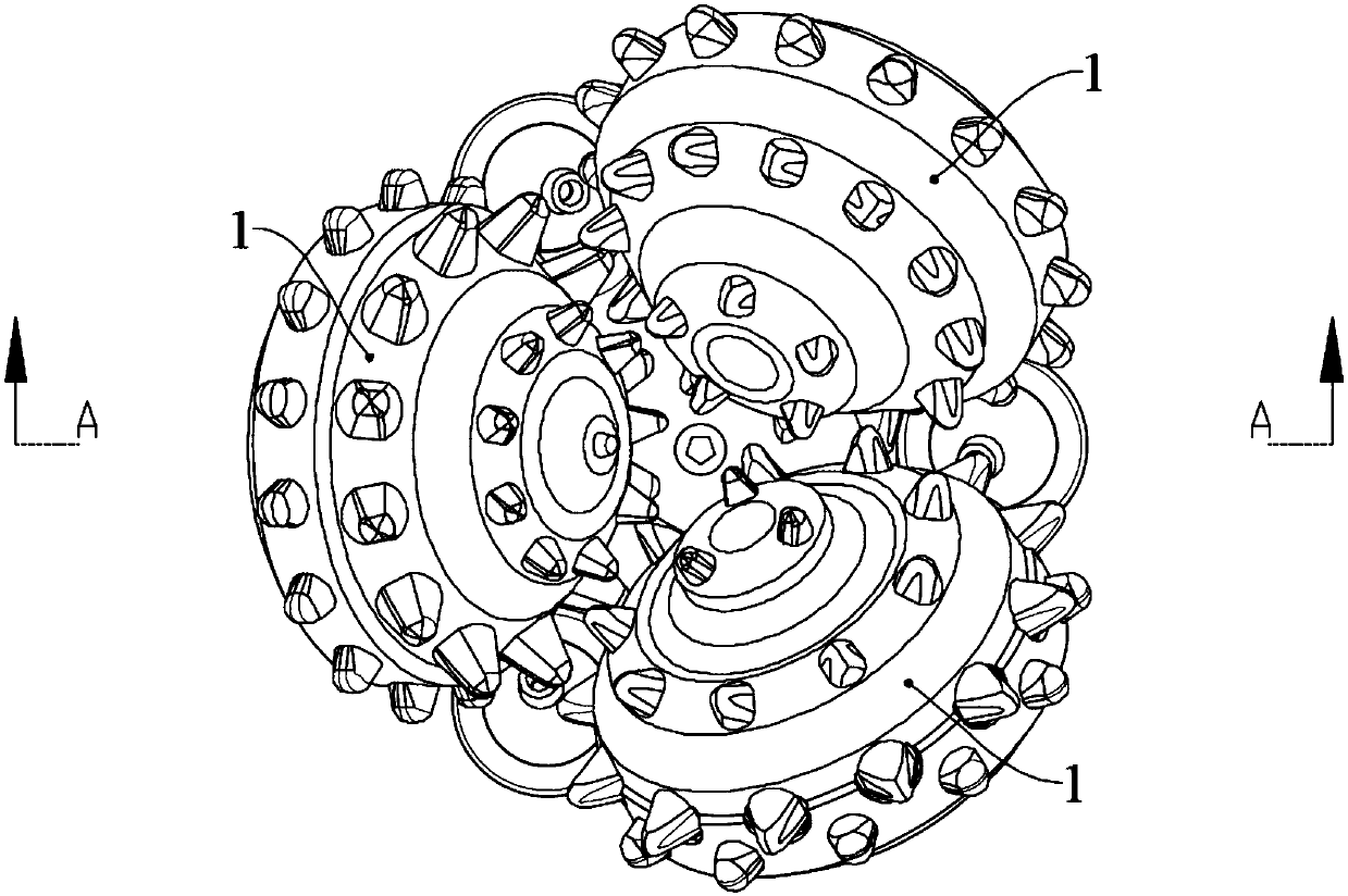
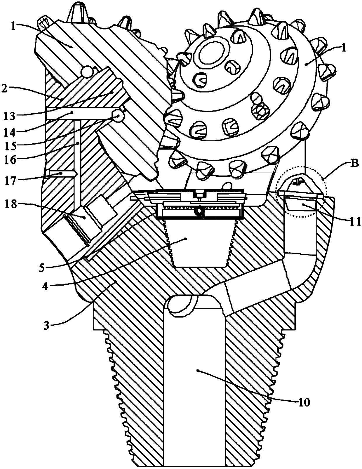
[0034]The split-type roller cone 1 drill bit of the present invention includes a palm seat 3, three palms 2 distributed in a ring are arranged on the upper end of the palm seat 3, and any tooth palm 2 is rotatably connected with a cone 1; the tooth palm 2 and the palm seat 3 The middle part of the palm seat 3 is provided with a placement groove 310, the inner wall of the lower end of the placement groove 310 is provided with a first internal thread 320, and the middle part of the palm seat 3 is provided with a compression unit for compressing the tooth palm 2. The lower end of the unit is connected with a connecting end that matches with the first internal thread 320 .
[0035] After adopting the above-mentioned technical scheme, the tooth palm 2 and the palm seat 3 of the present invention are arranged separately, which is convenient to remove the cone 1 along with the tooth palm 2, and facilitates the maintenance of a certain cone 1. A certain tooth palm 2 or cone 1 on the b...
Embodiment 2
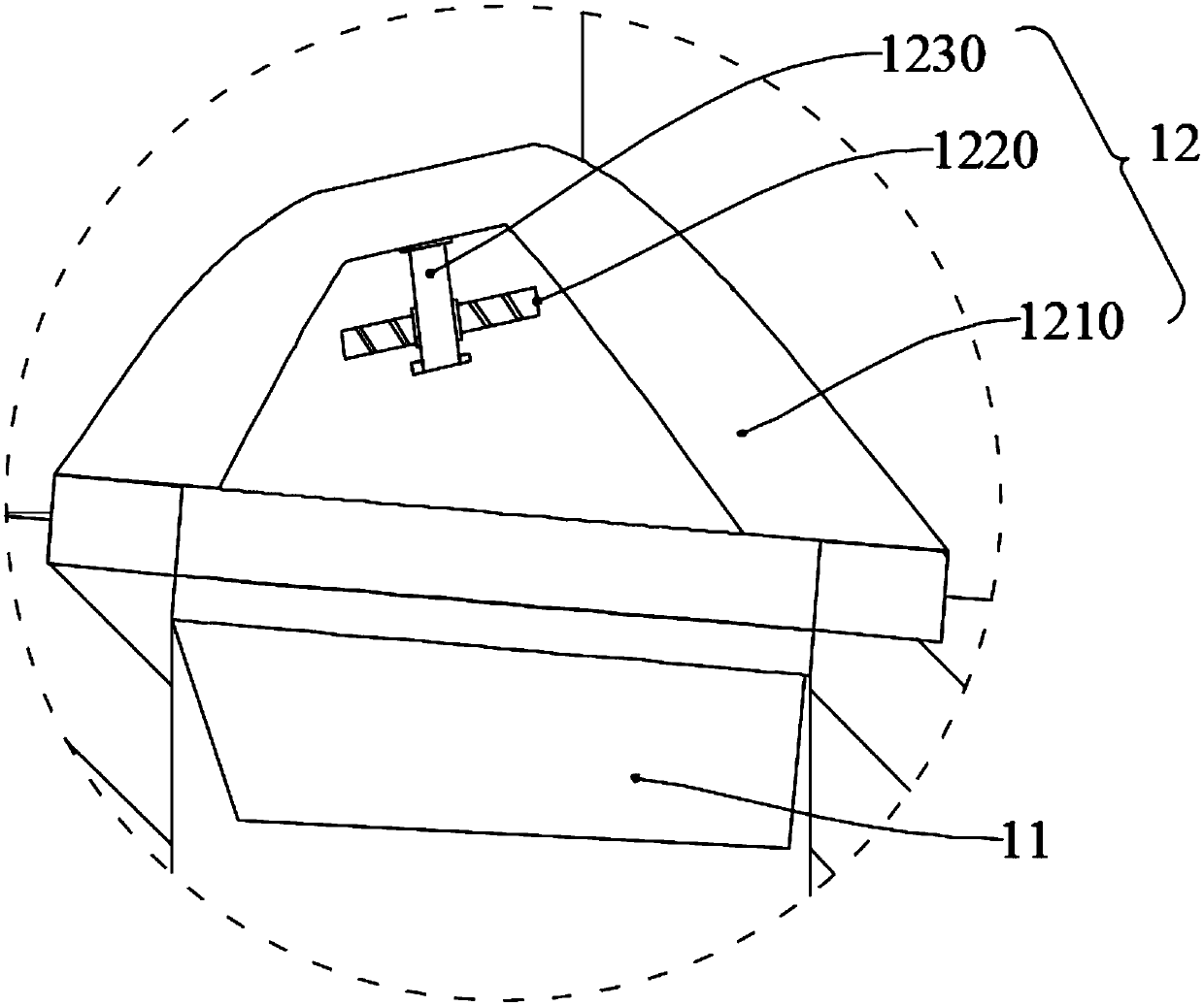
[0037] This embodiment is further optimized on the basis of Embodiment 1 as follows: the lower end of the tooth palm 2 is an inclined surface, and at least one slider is provided at the lower end of the tooth palm 2, the cross-sectional shape of the slider is dovetail or I-shaped, and the palm seat 3 is provided with a chute 330 matching with the slider, the upper end of the chute 330 runs through the outer wall of the palm rest 3, and the lower end of the chute 330 does not go through the side wall of the palm rest 3.
[0038] After adopting the above-mentioned technical scheme, the contact surface between the tooth palm 2 and the palm seat 3 is an inclined surface, and at least one slider is used to ensure that the tooth palm 2 and the palm seat 3 can be accurately positioned when they are installed, and quick installation can be realized. The shape is dovetail or I-shaped, which can be accurately positioned and quickly installed, while ensuring the integrity of the tooth pal...
Embodiment 3
[0040] This embodiment is further optimized on the basis of Embodiment 1 as follows: the compression unit includes a placement box 5, an adjustment disc 6, a small bevel gear 7 and a compression block 8; the placement box 5 is arranged in the placement groove 310, and the adjustment The disk 6 is set inside the placement groove 310, the upper end of the adjustment disk 6 is provided with an Archimedes spiral groove 610, the lower end of the adjustment disk 6 is provided with a large bevel gear 620, and a plurality of small bevel gears 7 are rotated and installed and run through the bottom of the placement box 5. On the outer wall, the small bevel gear 7 and the large bevel gear 620 mesh with each other. The upper end of the adjustment disc 6 is provided with three compression blocks 8, and the lower end of any compression block 8 is provided with multiple arcs that cooperate with the Archimedes spiral groove 610. shaped protrusion 830, any pressing block 8 is connected with a f...
PUM
 Abstract
Description
Claims
Application Information
 - R&D
- Intellectual Property
- Life Sciences
- Materials
- Tech Scout
- Unparalleled Data Quality
- Higher Quality Content
- 60% Fewer Hallucinations
Browse by: Latest US Patents, China's latest patents, Technical Efficacy Thesaurus, Application Domain, Technology Topic, Popular Technical Reports.
© 2025 PatSnap. All rights reserved.Legal|Privacy policy|Modern Slavery Act Transparency Statement|Sitemap|About US| Contact US: help@patsnap.com