A plastic bottle injection molding machine

A technology for injection molding machines and plastic bottles, which is applied to household appliances, other household appliances, household components, etc. It can solve the problems of increasing the footprint of injection molding machines and reducing the space utilization efficiency of injection molding machines, so as to improve injection molding production efficiency and shorten the production time. length, the effect of reducing the slip distance

Active Publication Date: 2020-12-29
杭州永星塑料包装有限公司
View PDF1 Cites 1 Cited by
  • Summary
  • Abstract
  • Description
  • Claims
  • Application Information

AI Technical Summary

Problems solved by technology

Since the existing fixed platen and movable platen are usually arranged at intervals along the direction of the tie rods, the sliding of the fixed platen and the movable platen in the direction of the tie rods increases the length of the injection molding machine, thereby increasing the floor space of the injection molding machine and reducing the injection molding time. machine space efficiency

Method used


Image

  • A plastic bottle injection molding machine
  • A plastic bottle injection molding machine
  • A plastic bottle injection molding machine

Examples


Embodiment

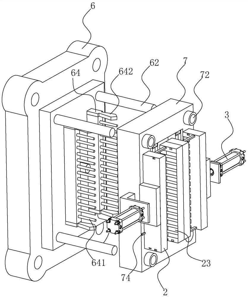
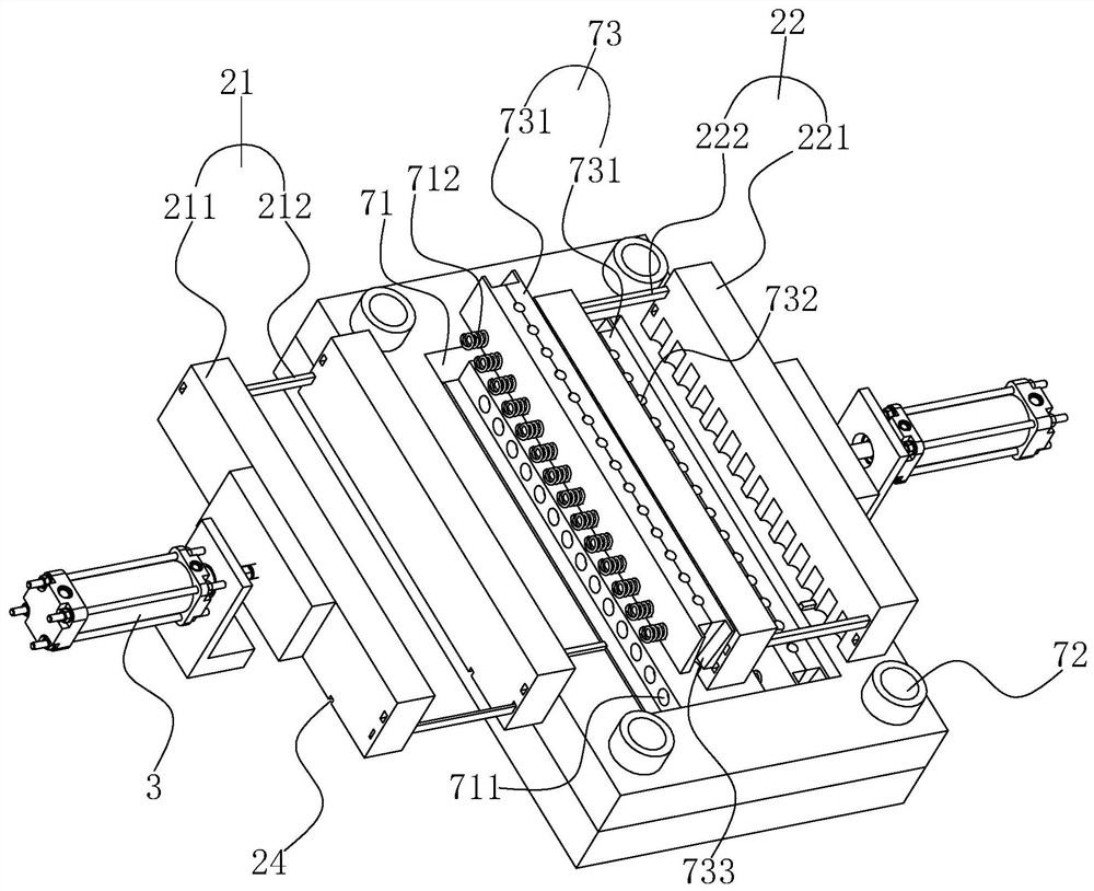
[0035] Embodiment, a kind of plastic bottle injection molding machine, as figure 1 As shown, it includes a machine 1, a forming mold 2 fixed on the machine 1, and a driving cylinder 3 for driving the forming mold 2 to open and close the mold. The forming mold 2 is connected with a number of injection pipes.

[0036] Such as figure 1As shown, the machine 1 is in the shape of a rectangular table, and the two ends of the machine 1 in the length direction are respectively vertically fixed with side plates 4 and detection plates 5 , both of which are in the shape of rectangular plates. Four sliding columns 41 are fixed horizontally between the side plate 4 and the detection plate 5 . The sliding columns 41 are cylindrical, and their two ends are respectively fixed at the four corners of the side plate 4 and the detection plate 5 . A seat plate 6 is slidably disposed on the sliding post 41 . The seat plate 6 is in the shape of a rectangular plate and the four sliding posts 41 are r...


PUM


Abstract

The invention discloses a plastic bottle injection molding machine, and relates to the technical field of application of injection molding equipment. The technical problems that a fixed mold plate anda movable mold plate slide in the pull rod direction, consequently, the length of the injection molding machine is increased, and the space utilization efficiency is reduced are solved. According tothe technical key points, the plastic bottle injection molding machine comprises a machine table, a forming mold fixed to the machine table, and a driving air cylinder for driving the forming mold tobe opened and closed, the forming mold comprises a left movable mold and a right movable mold, the left movable mold comprises a pair of left mold plates vertically arranged in a spaced mode, and a left connecting rod is fixed between the left mold plates; and the right movable mold comprises a pair of right mold plates arranged in a spaced mode, wherein the right mold plates and the left mold plates are located on the same vertical plane, a right connecting rod is fixed between the right mold plates, mold cavities are formed in the opposite faces of the left mold plates and the right mold plates correspondingly, and mold columns matched with the mold cavities for injection molding are arranged at the positions, between each left mold plate and the corresponding adjacent right mold plate,of a bottom plate. The plastic bottle injection molding machine has the advantages that the space utilization efficiency of the injection molding machine is improved while the forming efficiency of the injection molding machine is ensured.

Description

technical field [0001] The invention relates to the technical field of injection molding equipment application, more specifically, it relates to a plastic bottle injection molding machine. Background technique [0002] The Chinese patent with the notification number CN103302822B discloses a kind of injection molding machine for producing plastic bottle caps. The injection molding machine includes a machine platform. The templates are connected by pull rods, and the movable template and the fixed template are closed to form several cavities for molding the plastic bottle caps. The injection molding machine also includes a pick-up device, and the pick-up device includes a pick-up plate , the pick-up plate is provided with a clamping structure capable of fixing or loosening the plastic bottle cap, and the machine table is fixed with a lifting mechanism capable of driving the pick-up plate to move up and down. [0003] In the prior art, similar to the above-mentioned injection ...

Claims


Application Information

Patent Timeline
Patent Type & Authority Patents(China)
IPC IPC(8): B29C45/67B29C45/26B29C45/27B29C45/17B29C45/76
CPCB29C45/1769B29C45/26B29C45/27B29C45/67B29C45/76B29L2031/7158
Inventor 周锡永
Owner 杭州永星塑料包装有限公司
Why Eureka
Try Eureka