
A dual-machine self-synchronously driven balanced vibrating crusher

A crusher, self-synchronizing technology, applied in grain processing and other directions, can solve the problems of strict qualifications of installers and operators, complicated installation process, easy wear of jaw plates, etc., and achieves increased crushing stroke and compact mechanical structure. , the effect of small vertical stroke

Active Publication Date: 2020-08-04
NORTHEASTERN UNIV LIAONING
View PDF6 Cites 0 Cited by
  • Summary
  • Abstract
  • Description
  • Claims
  • Application Information

AI Technical Summary

Problems solved by technology

[0004] At present, the currently used crushers still have the following disadvantages: the crushing chamber has only one movable jaw body, which is driven by a motor to work in one direction, and its vertical stroke is relatively large. Suffering local grinding and peeling, thus giving a reaction force to the jaw plate and making the jaw plate easier to wear. At the same time, most crushers use high-power motors as power sources, and the energy consumption accounts for about 50% of the power consumption of the whole plant in the concentrator. Its working process has low crushing rate, high energy consumption and poor stability, which does not meet the national requirements for energy saving, emission reduction and environmental protection
In addition, it is necessary to lay out lines before use, the installation process is complicated, and there are strict conditions for the qualifications of installers and operators

Method used


Image

  • A dual-machine self-synchronously driven balanced vibrating crusher
  • A dual-machine self-synchronously driven balanced vibrating crusher
  • A dual-machine self-synchronously driven balanced vibrating crusher

Examples


Embodiment Construction

[0022] The technical solution of the present invention will be described in detail below in conjunction with the accompanying drawings and specific embodiments.

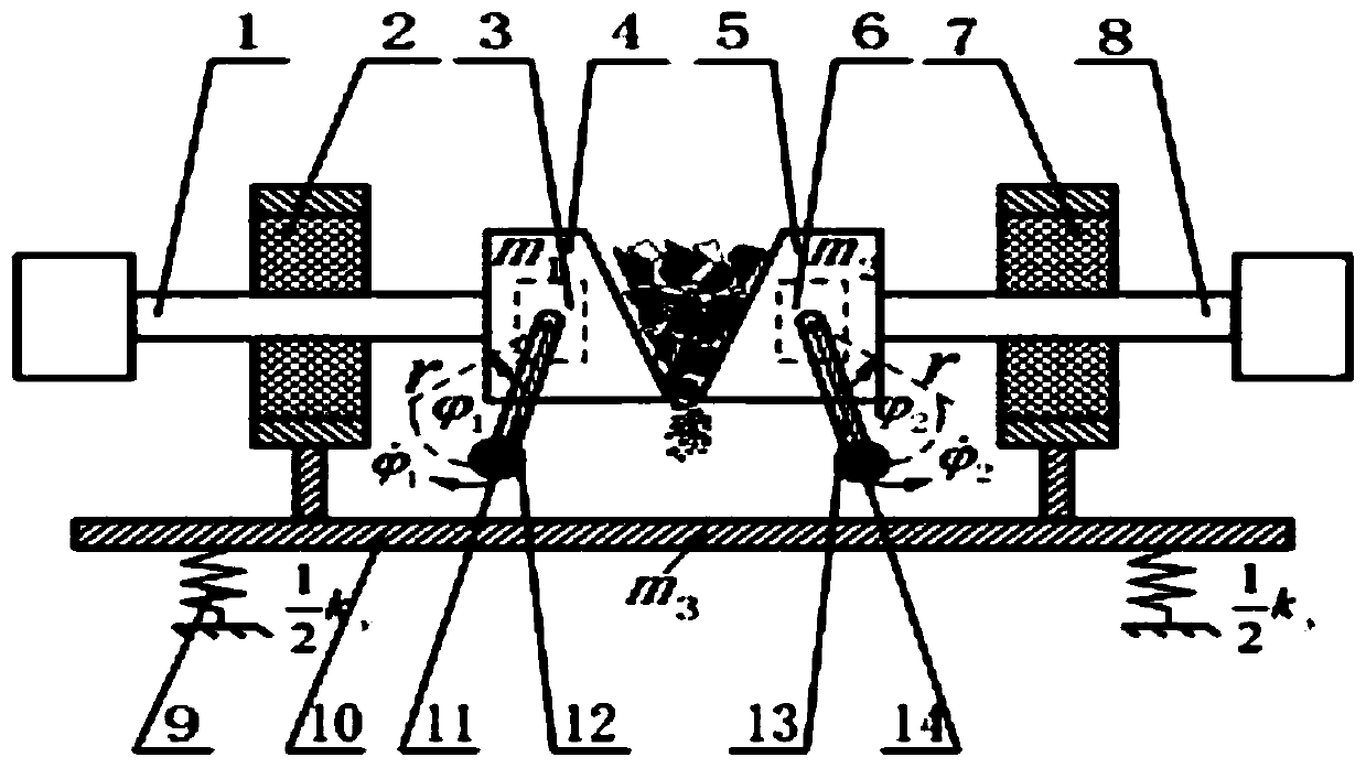
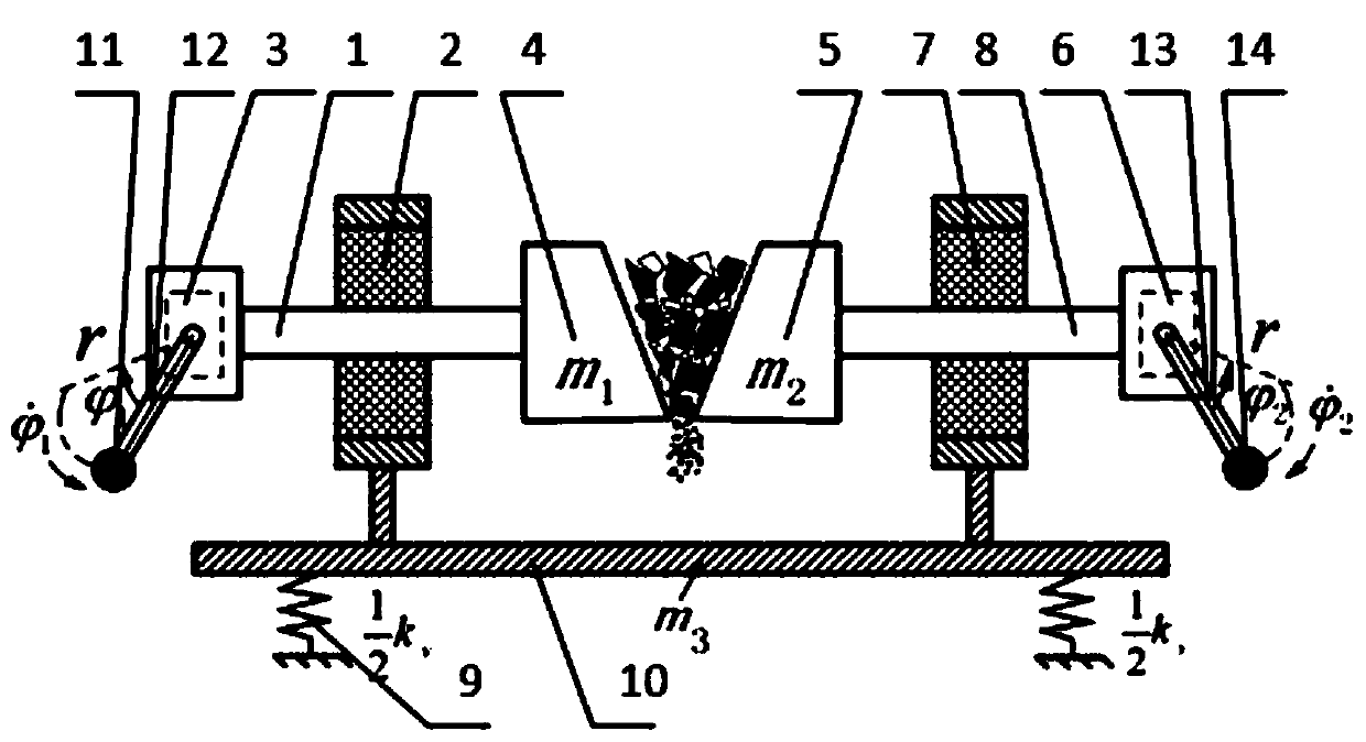
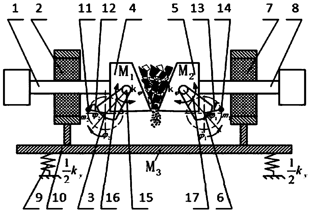
[0023] figure 1 Among them, the left vibrator 3 and the right vibrator 6 are a pair of symmetrically arranged vibrators, the left pendulum ball 11 and the left pendulum rod 12 are installed on the left vibrator 3, the right pendulum rod 13 and the right pendulum ball 14 Installed on the right vibrator 6, the left vibrator 3 is built into the left jaw plate 4, the left jaw plate 4 is connected with the left main vibration spring 2 through the left support body 1, and the right vibrator 6 is built into the right jaw plate 5, the right jaw plate 5 is connected with the right main vibration spring 7 through the right support body 8, and the two main vibration springs are respectively installed on both sides of the vibration isolation body 10, and the vibration isolation body 10 is connected to the foundation by the vibra...


PUM


Abstract

The invention belongs to the field of self-synchronous vibration machinery and provides a dual-machine self-synchronous drive balanced vibration crusher, which includes two sets of vibrators, two sets of main vibration springs, two supports, two jaw plates, and two sets of reducers. Vibration spring and vibration isolation body; driven by the self-synchronization principle of the two machines, when the material is broken, the two exciters are driven by the AC motor to drive the eccentric rotor to perform reverse high-speed rotation to generate the exciting force, thereby driving the movable jaw to achieve reverse rotation. The relative motion of the phase realizes that the forces of the two movable jaws in the horizontal direction cancel each other out, achieves a self-balancing state, and ensures that the load transmitted in the horizontal direction is minimized, while achieving the crushing of the material between the two movable jaws. . This invention combines the sub-resonance principle and the self-synchronization principle of dual exciters, and uses the vibration crushing method to achieve very high crushing strength of the crusher, enhance the stability of the system, and achieve energy saving of the crusher. This crusher can achieve a relatively large crushing ratio and can crush super-hard materials.

Description

technical field [0001] The invention belongs to the field of self-synchronous vibrating machinery, and relates to a dual-machine self-synchronously driven balanced vibrating crusher. Background technique [0002] A crusher is a device that crushes mined natural stone according to specific requirements. In 1858, American engineer E.W.Blake invented and manufactured the first jaw crusher; the traditional jaw crusher is widely used in various fields of industry because of its advantages of convenient operation, simple structure, easy maintenance, reliable operation and low price. There are a wide range of applications. The vibrating crusher uses the principle of vibration to generate the exciting torque through the vibrating motor, so that the stones vibrate according to a certain rule, and the materials are crushed through mutual collision and friction. Since the appearance of the first crusher, the production efficiency of the factory has been improved to a certain extent. ...

Claims


Application Information

Patent Timeline
Patent Type & Authority Patents(China)
IPC IPC(8): B02C19/16B02C1/04
CPCB02C1/043B02C19/16
Inventor 张学良张晨李明张旭李振民马辉闻邦椿
Owner NORTHEASTERN UNIV LIAONING
Learn More