Electromagnetic clutch control method

An electromagnetic clutch, current technology, applied in the direction of magnetic drive clutch, clutch, non-mechanical drive clutch, etc., to achieve the effect of quick engagement in place

Active Publication Date: 2019-04-12
ZHUHAI JUNCHI TECH CO LTD
View PDF4 Cites 0 Cited by
  • Summary
  • Abstract
  • Description
  • Claims
  • Application Information

AI Technical Summary

Problems solved by technology

[0003] The purpose of the present invention is to propose a method for controlling the electromagnetic clutch to solve the problem of the separation delay of the electromagnetic clutch, thereby realizing more accurate control of the electromagnetic clutch

Method used


Image

  • Electromagnetic clutch control method
  • Electromagnetic clutch control method
  • Electromagnetic clutch control method

Examples


Embodiment Construction

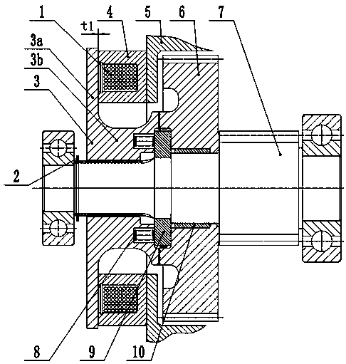
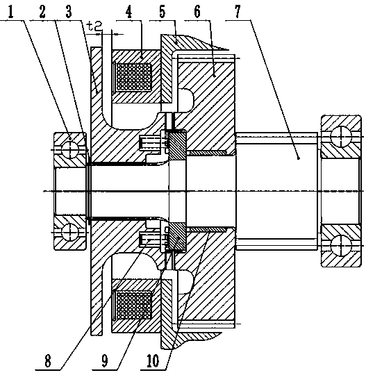
[0030] refer to figure 1 , shows a schematic diagram of the structure of the electromagnetic clutch according to the present application when it is engaged. The electromagnetic clutch includes a coil 1 , a movable disc 3 , a coil support part 4 , a casing 5 , a transmission gear 6 , a shaft 7 , a return element 8 and a limit block 9 .

[0031] The movable disk 3 has a head 3a and an extension 3b. The movable disk 3 is connected with the shaft 7 by, for example, splines, so that the shaft 7 can support the movable disk 3 and the movable disk 3 can slide along the axial direction of the shaft 7 . The end face of the extension part 3b is provided with face teeth, and the end face of the extension part 3b can be selectively engaged and disengaged from the transmission gear 6 through the engagement and disengagement of the end face teeth, thereby transmitting the power of the transmission gear 6 to the shaft 7 . Also provided in the end face of the extension 3 b is a recess for r...


PUM


Abstract

The invention relates to an electromagnetic clutch control method. An electromagnetic clutch comprises a coil, a movable disc, a coil supporting portion, a transmission gear, a shell, a shaft, a return element and a limit block. According to the electromagnetic clutch control method, the current input into the coil of the electromagnetic clutch is controlled according to the demands for disconnection and connection of the electromagnetic clutch, accordingly, the problem of separation delay of the electromagnetic clutch is solved, and therefore, control over the electromagnetic clutch is more precise.

Description

technical field [0001] The invention relates to the field of electromagnetic clutches, in particular to the field of electromagnetic clutches of vehicles or power machinery, and specifically relates to a method for controlling electromagnetic clutches of vehicles. Background technique [0002] Electromagnetic clutches are widely used in various fields, especially in vehicle transmissions. Electromagnetic clutches are used in transmissions to shift gears, cut off power transmission, and the like. These operations require extremely precise control of the electromagnetic clutches, allowing the transmission or vehicle to perform the functions desired by the driver. However, the electromagnetic clutch in the prior art has the problem of inaccurate control. Specifically, when the current to the electromagnetic clutch is removed, the electromagnetic clutch cannot be returned in time due to the residual magnetism. Contents of the invention [0003] The purpose of the present inv...

Claims


Application Information

Patent Timeline
IPC IPC(8): F16D27/09F16D27/14
CPCF16D27/09F16D27/14
Inventor 王慧敏
Owner ZHUHAI JUNCHI TECH CO LTD
Why Eureka
Try Eureka