
A smart home lock

A technology of smart home and mounting seat, applied in the field of locks, can solve the problems of unstable docking, unfavorable cleaning, affecting installation efficiency, etc., and achieve the effects of convenient disassembly and replacement, convenient alignment connection, and convenient connection and positioning.

Active Publication Date: 2020-11-10
中山市海诗蔓五金有限公司
View PDF13 Cites 0 Cited by
  • Summary
  • Abstract
  • Description
  • Claims
  • Application Information

AI Technical Summary

Problems solved by technology

[0003] However, existing smart home locks still have some deficiencies in actual use. For example, the fingerprint reading area is exposed on the outer surface of the mounting seat, and after repeated use, it is easy to be stained with dust and oil. Cleaning will affect the fingerprint reading and bring a lot of trouble to the normal opening of the door. Wiping with a rag is cumbersome and easy to forget. At the same time, it is not convenient to store the cleaning solution. It is not conducive to keeping it clean when it is squeezed out when cleaning is needed. The use effect is not ideal. The installation through the home lock usually uses two bolts combined with the fixing seat to install on the door. The length of the bolts used is required to be fixed. In actual operation, if the bolts are too long, they cannot be docked with the door, and the bolts If it is too short, the exposed end after passing through the door is shorter, so that when docking the mounting seat, the gap with the door is small, it is inconvenient to watch the position, resulting in unstable docking and affecting installation efficiency

Method used


Image

  • A smart home lock
  • A smart home lock
  • A smart home lock

Examples


Embodiment Construction

[0035] The technical solutions in the embodiments of the present invention will be clearly and completely described below in conjunction with the accompanying drawings in the embodiments of the present invention; obviously, the described embodiments are only part of the embodiments of the present invention, not all of them. For example, based on the embodiments of the present invention, all other embodiments obtained by persons of ordinary skill in the art without making creative efforts belong to the scope of protection of the present invention.

[0036] In the description of the present utility model, it should be noted that the orientation or positional relationship indicated by the terms "upper", "lower", "inner", "outer", "top / bottom" etc. are based on the Orientation or positional relationship is only for the convenience of describing the utility model and simplifying the description, and does not indicate or imply that the device or element referred to must have a specif...


PUM


Abstract

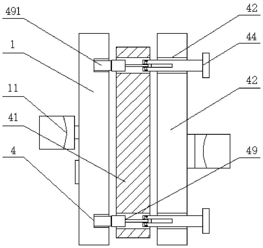
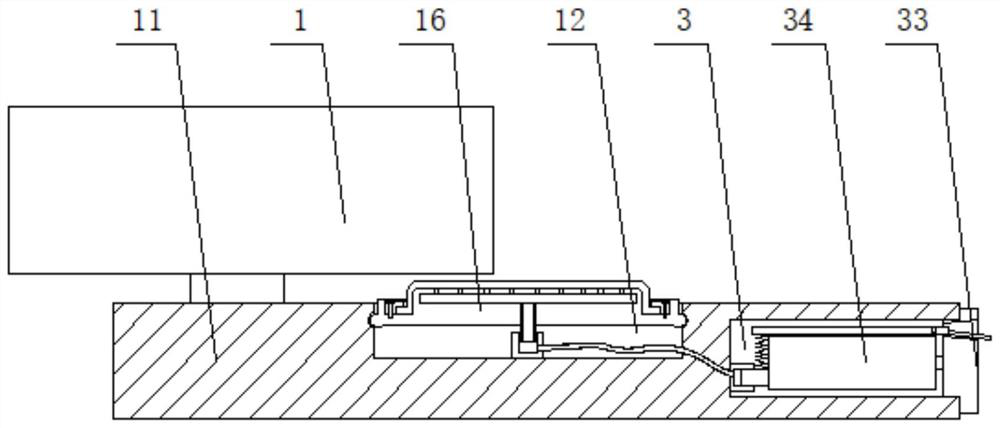
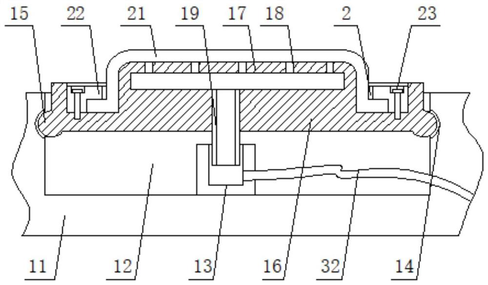
The invention discloses an intelligent household lock, and belongs to the field of locks. The intelligent household lock comprises a mounting base, a handle is rotationally connected to the outer surface of the mounting base, and a first connecting groove is formed in the front end of the inner side surface of the handle; a first connecting pipe is arranged on the inner bottom surface of the firstconnecting groove, elastic clamping grooves are both formed in the surfaces of the two sides of the interior of the first connecting groove, the inner side surfaces of the elastic clamping grooves are connected with a mounting plate in a clamped mode through elastic clamping heads, and a supporting boss is arranged on the upper surface of the mounting plate; and the lower surfaces of communication holes are connected to the inner side surface of the first connecting pipe through a first insertion pipe in a sliding mode, an annular groove is formed in the upper surface of the mounting plate, and a cleaning sponge strip is slidably connected to the inner side surface of the annular groove. Through the mounting plate clamped inside the first connecting groove, and a soft rubber bottle placedinside a second connecting groove, a pressing rod structure supported by a spring is combined, so that a cleaning liquid is conveniently extruded onto the cleaning sponge strip for wiping.

Description

technical field [0001] The utility model relates to the field of locks, in particular to an intelligent home lock. Background technique [0002] In today's daily life, smart home has become a fashion trend. Among them, the home lock with fingerprint function is the most widely used, which can open the door by reading the fingerprint, which is convenient for people's daily life. [0003] However, existing smart home locks still have some deficiencies in actual use. For example, the fingerprint reading area is exposed on the outer surface of the mounting seat, and after repeated use, it is easy to be stained with dust and oil. Cleaning will affect the fingerprint reading and bring a lot of trouble to the normal opening of the door. Wiping with a rag is cumbersome and easy to forget. At the same time, it is not convenient to store the cleaning solution. It is not conducive to keeping it clean when it is squeezed out when cleaning is needed. The use effect is not ideal. The ins...

Claims


Application Information

Patent Timeline
Patent Type & Authority Patents(China)
IPC IPC(8): E05B49/00
CPCE05B49/00
Inventor 韩正宁
Owner 中山市海诗蔓五金有限公司
Learn More