
Aircraft

A technology of aircraft and hinges, which is applied in the aviation field, can solve the problems of high complexity of deformation devices, narrow installation space of deformation devices, severe load, etc., and achieve the effect of simple driving form, convenient maintenance, and variable sweep angle

Inactive Publication Date: 2019-04-12
XIAN AIRCRAFT DESIGN INST OF AVIATION IND OF CHINA
View PDF5 Cites 2 Cited by
  • Summary
  • Abstract
  • Description
  • Claims
  • Application Information

AI Technical Summary

Problems solved by technology

This kind of aircraft has problems such as narrow installation space of the deformation device, high complexity of the deformation device, and severe loading.

Method used


Image

  • Aircraft
  • Aircraft
  • Aircraft

Examples


Embodiment Construction

[0027] In order to make the purpose, technical solutions and advantages of the embodiments of the present invention more clear, the technical solutions in the embodiments of the present invention will be clearly and completely described below in conjunction with the drawings in the embodiments of the present invention. Apparently, the described embodiments are some, but not all, embodiments of the present invention. Based on the embodiments of the present invention, all other embodiments obtained by persons of ordinary skill in the art without making creative efforts belong to the protection scope of the present invention.

[0028] Features and exemplary embodiments of various aspects of the invention are described in detail below. In the following detailed description, numerous specific details are set forth in order to provide a thorough understanding of the present invention. It will be apparent, however, to one skilled in the art that the present invention may be practice...


PUM


Abstract

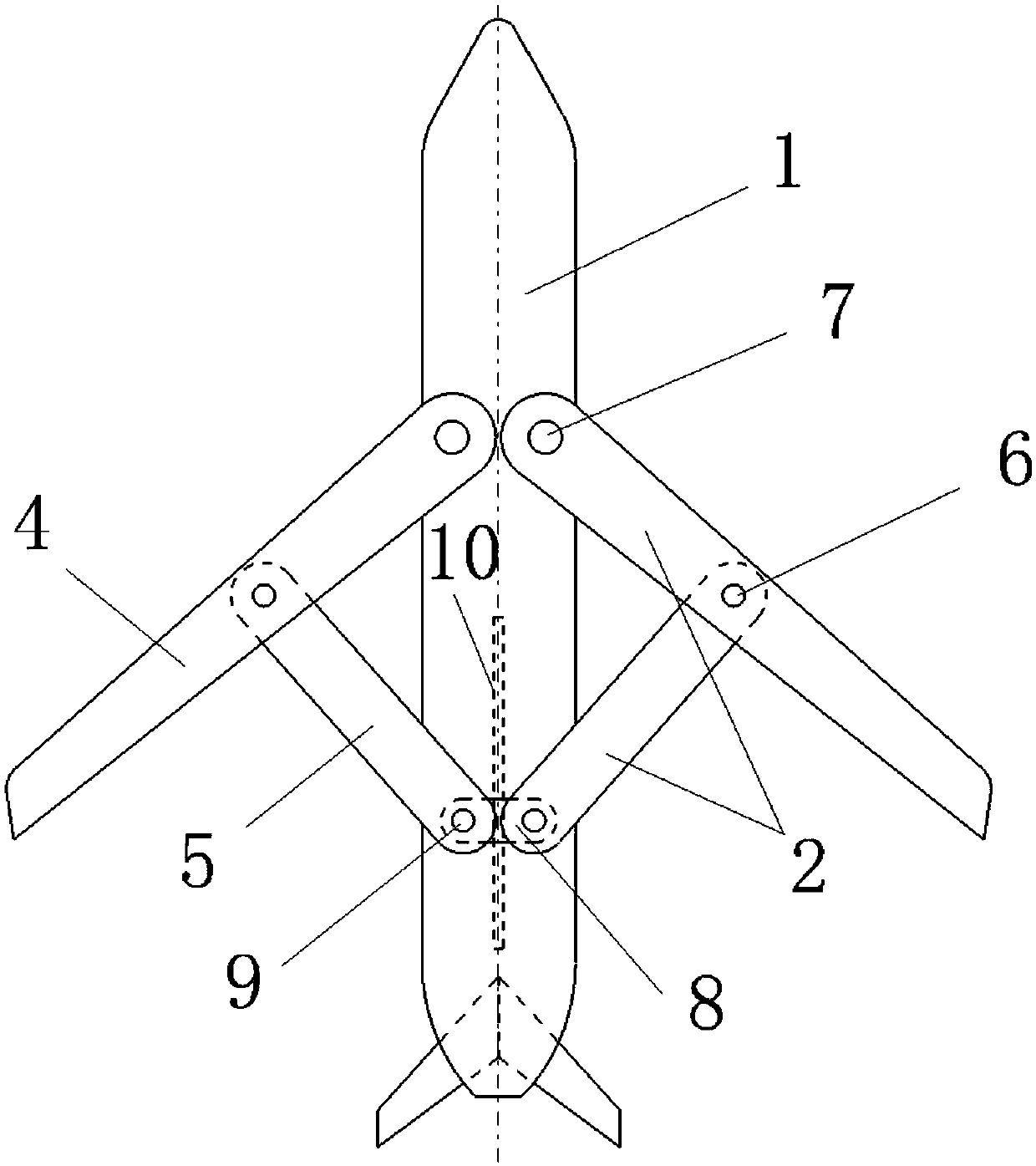
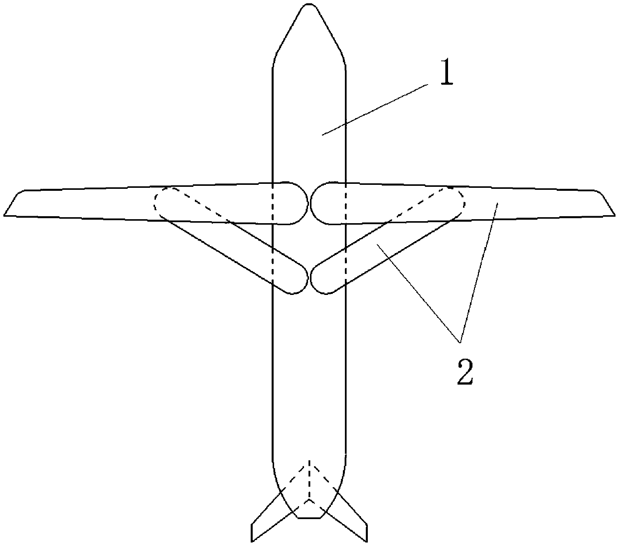
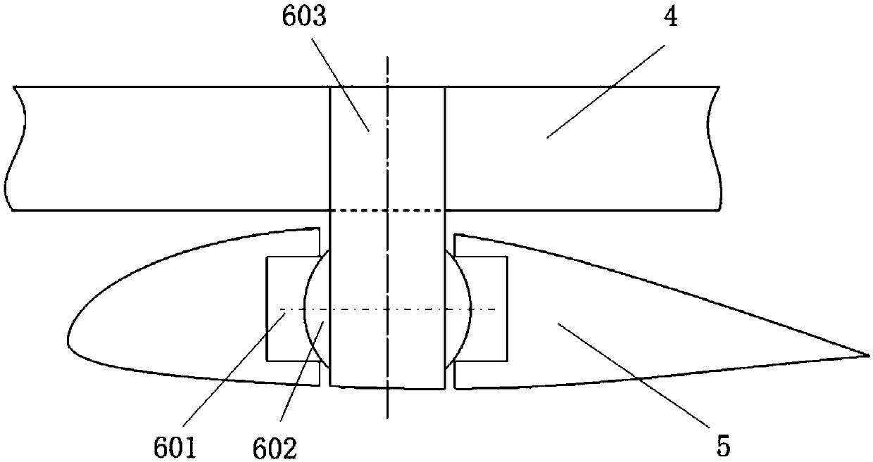
The invention discloses an aircraft comprising a body and wings. The wings include one pair of main sweepback wing planes and one pair of secondary sweepforward wing planes. The main wing planes and the secondary wing planes are connected by wing links. The main wing planes and the body are connected by front hinges. The body includes a sliding block and a sliding block driving unit; and the sliding block driving unit is controlled to drive the sliding block to make forward and backward movement. The secondary wing planes and the sliding block are connected by rear hinges. The sliding block isdriven by the sliding block driving unit to slide forward and backward along the body, thereby changing the included angles between the main wing planes and the secondary wing planes and the body. According to the invention, the included angles between the wings and the body can be changed; and the optimal pneumatic lift-to-drag efficiency is obtained.

Description

technical field [0001] The invention relates to the field of aviation technology, in particular to an aircraft. Background technique [0002] The angle between the wing and the fuselage of conventional aircraft is fixed. For example, an aircraft flying at a low speed adopts a form where the wings are perpendicular to the fuselage in order to obtain greater lift; However, the speed of the aircraft is not constant during the entire flight process. In the entire speed range, only the aircraft whose angle between the wing and the fuselage is fixed at a specific speed can obtain Excellent aerodynamic lift and drag efficiency. [0003] According to the applicant's research, it is found that some fighters or bombers install very complex deformation devices at the connection between the wings and the fuselage, and the angle between the wings and the fuselage is driven to change. This kind of aircraft has the problems of narrow installation space of the deformation device, high co...

Claims


Application Information

Patent Timeline
Patent Type & Authority Applications(China)
IPC IPC(8): B64C3/40B64C39/08
CPCB64C3/40B64C39/08
Inventor 周正光贾利勇韩杰王启
Owner XIAN AIRCRAFT DESIGN INST OF AVIATION IND OF CHINA
Learn More