
Three-dimensional dynamic positioning system for mobile dual-plane X-ray system

A dynamic positioning and optical system technology, which is applied in the fields of radiological diagnosis instruments, medical science, diagnosis, etc., can solve problems such as calibration and positioning of dual X-ray fluoroscopic imaging systems

Active Publication Date: 2019-04-12
SHANGHAI INNOMOTION
View PDF18 Cites 3 Cited by
  • Summary
  • Abstract
  • Description
  • Claims
  • Application Information

AI Technical Summary

Problems solved by technology

[0010] For this reason, currently only the concept of dual X-ray fluoroscopy imaging system to obtain three-dimensional images of joints has been proposed. However, in the specific application of the dual X-ray fluoroscopy imaging system, there is no relevant technology on how to calibrate and position the dual X-ray fluoroscopy imaging system. disclosure

Method used


Image

  • Three-dimensional dynamic positioning system for mobile dual-plane X-ray system
  • Three-dimensional dynamic positioning system for mobile dual-plane X-ray system
  • Three-dimensional dynamic positioning system for mobile dual-plane X-ray system

Examples


Embodiment 1

[0042] The stereoscopic dynamic positioning system in this example includes a control device, a registration device, a single calibration device and a double calibration device; wherein the control device is used to control the first X-ray emitting device and the second X-ray emitting device to emit X-rays synchronously.

[0043] In a preferred solution, in order to prevent the X-rays emitted by the first X-ray emitting device and the second X-ray emitting device from producing optical interference, the control device controls the first X-ray emitting device and the second X-ray emitting device to emit X-rays asynchronously, such as The first X-ray emitting device is delayed by 0-10ms from the second X-ray emitting device.

[0044] The stereoscopic dynamic positioning system in this example is a three-level calibration realized by sequentially executing the registration device, single calibration device and double calibration device. Specifically, the execution of the registrat...

Embodiment 2

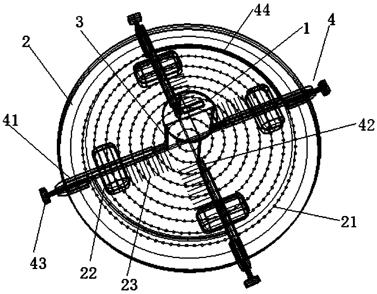
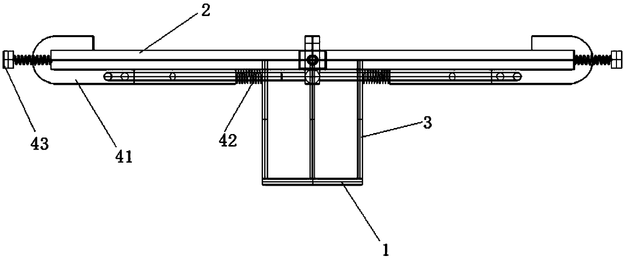
[0071] Based on Embodiment 1, this example describes in detail the structure of the single calibration device, as figure 1 , figure 2 and image 3As shown, the single calibration device includes a first circular plexiglass plate 1, a second circular plexiglass plate 2, several support columns 3 and an adjustment mechanism 4, wherein the symmetrical equipment around the center of the first circular plexiglass plate 1 has Some holes, the second circular plexiglass plate is also uniformly provided with some holes 21, and the arrangement of some holes 21 is light diffusion characteristics, and the two ends of some support columns 3 are respectively connected to the first circular plexiglass plate 1 And on the second circular plexiglass plate 2; the adjustment mechanism 4 is installed on the second circular plexiglass plate 2, when the single calibration device is installed on the first / second X-ray receiving device by the adjustment mechanism 4, the adjustment mechanism 4 It is...


PUM


Abstract

The invention discloses a three-dimensional dynamic positioning system for a mobile dual-plane X-ray system. The mobile dual-plane X-ray system comprises a first X-ray system and a second X-ray system; the three-dimensional dynamic positioning system comprises a control device, an registration device, a single-calibration device and a double-calibration device; and the control device controls radiation emitters and radiation receivers in the first X-ray system and the second X-ray system to lift, rotate, pitch or / and shift according to feedbacks from the registration device, the single-calibration device or / and the double-calibration device until completion of spatial positioning between the first X-ray system and the second X-ray system. The three-dimensional dynamic positioning system realizes accurate spatial positioning of the mobile dual-plane X-ray system by performing three-stage calibration; and thus, accurate use of the mobile dual-plane X-ray system is achieved.

Description

technical field [0001] The invention relates to the technical field of biplane X-ray irradiation, in particular to a mobile biplane X-ray stereoscopic dynamic positioning system. Background technique [0002] Joint motion analysis is a quantitative description of joint motion and a study of the geometric properties of joint motion. The so-called geometric properties of motion refer to the law that the geometric positions of the bones and other structures that make up the joints change with time in space. Through joint motion analysis, the joint motion data can be obtained intuitively, objectively and quantitatively, which can be used as the basis for judging and evaluating the joint motion function. Joint motion analysis has important clinical significance. Its functions include studying the kinematics and biomechanical properties of the joints, detecting the range of motion and stability of the joints, assisting in the diagnosis of various diseases from the perspective of...

Claims


Application Information

Patent Timeline
IPC IPC(8): A61B6/00
CPCA61B6/4411A61B6/4452A61B6/587
Inventor 王少白范云平皇甫良
Owner SHANGHAI INNOMOTION
Learn More