Magnetic liquid sealing device with heat conduction rods and heat dissipation sleeve

A magnetic liquid and sealing device technology, applied in the direction of engine sealing, engine components, mechanical equipment, etc., can solve the problems of inability to discharge heat in time, inconvenient production and practical use, and increase the structural complexity of the magnetic liquid sealing device. Fast heat dissipation effect, the effect of avoiding the deterioration of the sealing effect

Pending Publication Date: 2019-04-09
TSINGHUA UNIV
View PDF0 Cites 11 Cited by
  • Summary
  • Abstract
  • Description
  • Claims
  • Application Information

AI Technical Summary

Problems solved by technology

These devices all require a water cooling system, and water cooling requires water pumps and other supporting settings, which introduces additional space and maintenance costs
However, in the traditional magnetic liquid rotary sealing device, the heat generated by the magnetic liquid in the sealing gap cannot be discharged in time. A Peltier-cooled magnetic liquid sealing device disclosed in the prior art, by arranging a plurality of Peltier cooling devices on the regular polygonal shell, , the sealing device is cooled by Peltier after power on
[0004] Whether it is a magnetic liquid sealing device that uses water cooling or circuit cooling, it will increase the complexity of the structure of the magnetic liquid sealing device, which is not convenient for production and practical use.

Method used


Image

  • Magnetic liquid sealing device with heat conduction rods and heat dissipation sleeve

Examples


Embodiment

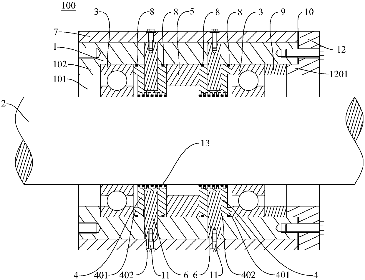
[0044] According to an embodiment of the present invention, a magnetic liquid sealing device 100 with a heat conduction rod and a heat dissipation sleeve includes a shaft housing 1, a rotating shaft 2, two bearings 3, two pole pieces 4, a permanent magnet 5, a heat conduction rod 6, a heat dissipation sleeve 7, a seal Ring 8, sleeve 9 and adjusting gasket 10.

[0045] The shaft housing 1 is provided with a shaft chamber 101, and the rotating shaft 2 is rotatably arranged in the shaft chamber 101. The rotating shaft 2 extends from one end of the shaft chamber 101 to the other end of the shaft chamber 101. Two bearings 3 are respectively sleeved on the rotating shaft 2. Above, two pole shoes 4 are sleeved on the rotating shaft 2 respectively, and are located between the two bearings 3, and a magnetic liquid 13 is adsorbed between the inner peripheral surface of each pole shoe 4 and the outer peripheral surface of the rotating shaft 2, and each pole There is a matching blind hole...


PUM

PropertyMeasurementUnit
Thicknessaaaaaaaaaa

Abstract

The invention discloses a magnetic liquid sealing device with heat conduction rods and a heat dissipation sleeve. The magnetic liquid sealing device comprises a shaft shell, a rotating shaft, two bearings, two pole shoes, a permanent magnet, the heat conduction rods and the heat dissipation sleeve, wherein a shaft chamber is arranged in the shaft shell, the rotating shaft is rotatably arranged inthe shaft chamber, the two bearings are both arranged on the rotating shaft in a sleeve mode, the two pole shoes are both arranged on the rotating shaft in a sleeve mode, and are located between the two bearings, magnetic liquid is adsorbed between the inner peripheral surface of each pole shoe and the outer peripheral surface of the rotating shaft, the outer peripheral surface of each pole shoe is provided with a matched blind hole extending along the radial direction of the pole shoe, the permanent magnet is arranged on the rotating shaft in a sleeve mode and is located between the two poleshoes, the heat conduction rods are inserted into the matched blind holes, the heat dissipation sleeve is arranged on the shaft shell in a sleeve mode, and the heat conduction rods are connected withthe heat dissipation sleeve through connecting pieces. According to the magnetic liquid sealing device with the heat conduction rods and the heat dissipation sleeve, water cooling or circuit heat dissipation is not needed, the structure is simple and the heat dissipation effect is good.

Description

technical field [0001] The invention relates to the field of mechanical engineering seals, in particular to magnetic liquid seals suitable for high-speed operating conditions. Background technique [0002] Sealing is a technical means to prevent medium leakage, and it is an extremely important part in engineering equipment. The sealing effect and reliability often directly determine the life and operation safety of the entire set of equipment. Once the seal fails, it will not only affect the normal operation of the equipment, but also seriously cause personal safety or huge economic losses. Magnetic liquid seals play an irreplaceable role in some high-end sealing fields because they can completely achieve zero leakage, and have the advantages of no pollution, high reliability, and long life. They are especially suitable for sealing key equipment with medium and low line speeds. [0003] In the case of high linear velocity, due to the shearing effect of the magnetic liquid, ...

Claims


Application Information

Patent Timeline
IPC IPC(8): F16J15/43
CPCF16J15/43
Inventor 李德才杨纪显陈思宇李倩孙睿刘霄李钲皓
Owner TSINGHUA UNIV
Why Eureka
Try Eureka