Eureka AIR delivers breakthrough ideas for toughest innovation challenges, trusted by R&D personnel around the world.

Planar motion structure

A technology of plane motion and moving blocks, applied in the direction of transmission, belt/chain/gear, mechanical equipment, etc., can solve the problems of wire sheath wear, inconvenient installation, excessive motor weight, etc., to achieve small invalid load, convenient installation, powerful effect

Pending Publication Date: 2019-04-09
泉州山外山科技有限公司
View PDF0 Cites 1 Cited by
  • Summary
  • Abstract
  • Description
  • Claims
  • Application Information

AI Technical Summary

Problems solved by technology

As the motor moves along with it, auxiliary equipment such as drag chains are required, and there are often phenomena such as equipment failure and leakage due to wear and tear on the sheath of the wire.
And the structure is relatively complicated, and the installation is very inconvenient
When the equipment needs to be upgraded, especially when the driving force is upgraded, and the size of the motor changes, it is often necessary to replace a lot of accessories, and some even cannot be upgraded because the motor is too heavy

Method used


Image

  • Planar motion structure
  • Planar motion structure
  • Planar motion structure

Examples


Embodiment Construction

[0029] The following are specific embodiments of the present invention and in conjunction with the accompanying drawings, the technical solutions of the present invention are further described, but the present invention is not limited to these embodiments.

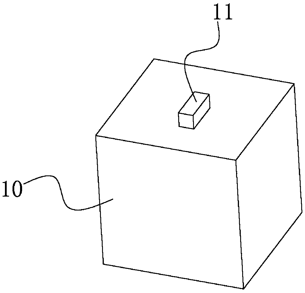
[0030] Such as figure 1 , figure 2 , image 3 , Figure 4 , Figure 5 As shown, a planar motion structure includes a frame 1, a pair of first screw rods 2 are arranged in parallel on the frame 1, and the first screw rods 2 are respectively provided with a driving device 3 for driving the first screw rod 2 to rotate. The helical direction of the screw thread of the rod 2 is opposite. The first screw rod 2 is provided with a screw nut module 4. The screw nut module 4 includes a first screw nut 5 and a rolling bearing 6 sleeved on the first screw nut 5. The rolling bearing 6 are connected by a connecting rod 7, and the first screw nuts 5 are connected by a synchronous piece 8. The synchronous piece 8 is provided with a m...


PUM


Abstract

The invention provides a planar motion structure and belongs to the technical field of planar motion structures. Through the planar motion structure, the problems that certain planar motion structurescan move in the X-axis direction and can also move in the Y-axis direction, and the motion structures are very complex are solved. The planar motion structure comprises a rack provided with a pair offirst screw rods parallelly. The first screw rods are correspondingly provided driving devices driving the first screw rods to rotate. The spiral directions of threads of the first screw rods are opposite. The first screw rods are sleeved with screw rod nut modules. The screw rod nut modules comprise first screw rod nuts and rolling bearings arranged on the first screw rod nuts in a sleeving mode. The rolling bearings are connected through a connecting rod. The first screw rod nuts are connected through a synchronous belt. A synchronous part is provided with a moving block. When rotating in the same direction, the first screw rod nuts drive the moving block to move through the synchronous part. The planar motion structure has the advantages of being simple in structure and the like.

Description

technical field [0001] The invention belongs to the technical field of plane motion structures, in particular to a plane motion structure. Background technique [0002] If all the components that make up the motion structure move in the same plane or in planes parallel to each other, the structure is called a planar motion structure. [0003] In some existing planar motion structures, if the object can move both along the X-axis direction and along the Y-axis direction, it is necessary to give a driving force in the X-axis direction and a driving force in the Y-axis direction. Larger equipment often needs to move with a heavy motor in a certain direction, which increases the load of the system and reduces the efficiency. As the motor moves along with it, auxiliary equipment such as tow chains are required, and there are often phenomena such as equipment failure and leakage due to wear and tear on the sheath of the wire. And the structure is relatively complicated, and the ...

Claims


Application Information

Patent Timeline
Patent Type & Authority Applications(China)
IPC IPC(8): F16H25/20F16H25/24
CPCF16H25/20F16H25/24F16H2025/2081
Inventor 吴东杨
Owner 泉州山外山科技有限公司
Why Eureka
Eureka Blog
Learn More