Multi-layer oil-gas separating device for automobile engine

A technology of automobile engine and separation device, applied in the direction of engine components, machines/engines, mechanical equipment, etc., can solve the problems of low separation efficiency, poor filtering effect, damage, etc.

Pending Publication Date: 2019-04-09
宁波赛铂睿特汽车部件有限公司
View PDF5 Cites 1 Cited by
  • Summary
  • Abstract
  • Description
  • Claims
  • Application Information

AI Technical Summary

Problems solved by technology

[0002] The oil-air separation device is connected to the engine cylinder head cover, because when the engine starts, the blow-by gas of the cylinder and the oil vapor will generate pressure, which will cause damage to the engine, so it is necessary to use the crankcase oil-air separation device to make it generate negative pressure, because There is a large amount of oil vapor in the gas extracted by the crankcase ventilation valve, so the oil-gas separation device mainly separates the oil vapor into

Method used


Image

  • Multi-layer oil-gas separating device for automobile engine
  • Multi-layer oil-gas separating device for automobile engine
  • Multi-layer oil-gas separating device for automobile engine

Examples


Embodiment Construction

[0036] The present invention will be further described below in conjunction with the accompanying drawings and specific embodiments.

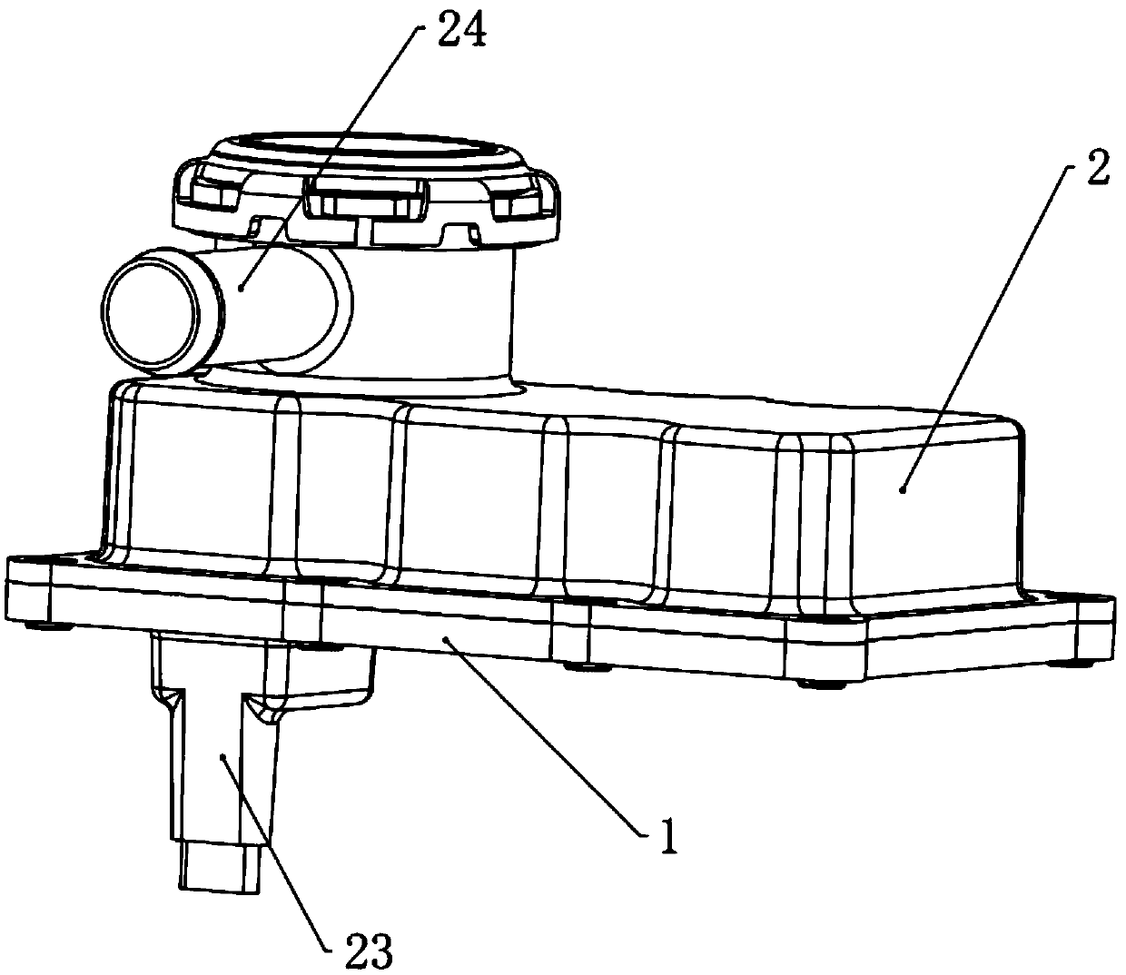
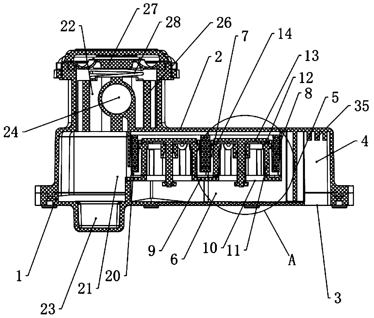
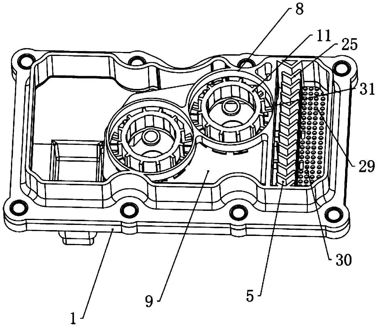
[0037] A multi-layer oil-gas separation device for an automobile engine, comprising a cover body, the cover body includes a detachably connected underframe and an upper cover 2, the underframe 1 is provided with a first air inlet 3, and the upper cover 2 is connected to the first The position corresponding to the air inlet is provided with a first channel 4, the side of the first channel 4 is provided with a second channel 5, the underframe 1 is provided with a first partition 9, and the cover is provided with a lower channel 6 and The upper channel 7, the lower channel 6 is located below the first partition 9, the upper channel 7 is located above the first partition, the chassis 1 is fixed with a first column ring 8, the first partition 9 is provided with a second air inlet 10, and the first partition 9 is provided with a third channel column ...


PUM


Abstract

The invention provides a multi-layer oil-gas separating device for an automobile engine. The purposes being high in separating efficiency, good in filtering effect and multiple in separating layers are achieved. The multi-layer oil-gas separating device for the automobile engine comprises a cover body, and the cover body comprises a chassis and an upper cover (2) which are detachably connected. The multi-layer oil-gas separating device for the automobile engine is characterized in that the chassis (1) is provided with a first air inlet (3), a first channel (4) is arranged on the portion, corresponding to the first air inlet, of the upper cover (2), and a second channel (5) is arranged on the side face of the first channel (4); the chassis (1) is provided with a first partition plate (9), the cover body is provided with a lower channel (6) and an upper channel (7), the lower channel (6) is located under the first partition plate (9), and the upper channel (7) is located over the first partition plate; and a first column ring (8) is fixedly arranged on the chassis (1).

Description

technical field [0001] The invention relates to the technical field of engine oil-gas separation, in particular to a multi-level oil-gas separation device for automobile engines. Background technique [0002] The oil-air separation device is connected to the engine cylinder head cover, because when the engine starts, the blow-by gas of the cylinder and the oil vapor will generate pressure, which will cause damage to the engine, so it is necessary to use the crankcase oil-air separation device to make it generate negative pressure, because There is a large amount of oil vapor in the gas extracted by the crankcase ventilation valve, so the oil-gas separation device mainly separates the oil vapor into oil and steam, so that the oil is collected in the pan and then flows back to the engine for reuse, and the steam flows to the engine for re-combustion to prevent Directly enter the atmosphere, causing air pollution. The separation device in the prior art is to realize the separat...

Claims


Application Information

Patent Timeline
IPC IPC(8): F01M13/04
CPCF01M13/04F01M2013/0438
Inventor 王彤母应超周寒剑
Owner 宁波赛铂睿特汽车部件有限公司
Why Eureka
Try Eureka