
Conductor section and stator assembly with same, and motor

A conductor and stator technology, applied in the shape/style/structure of winding conductors, electric components, electromechanical devices, etc., can solve problems such as poor insulation, easy to damage the surface of flat copper wires, small bending fillets, etc., to improve Reliability, reducing the risk of scratching the paint of adjacent copper wires, and facilitating soldering

Inactive Publication Date: 2019-04-05
BYD CO LTD
View PDF3 Cites 3 Cited by
  • Summary
  • Abstract
  • Description
  • Claims
  • Application Information

AI Technical Summary

Problems solved by technology

[0002] In the related art, in the hairpin coils of the same layer used in the plug-in stator assembly, the U-shaped head is bent inwardly towards one of the legs to form a bending step, which will make The end of the U-shaped part of the hairpin coil (that is, the hairpin end) becomes higher; in addition, because the bending fillet of the bending step is too small, it is easy to damage the paint on the surface of the flat copper wire, resulting in poor insulation

Method used


Image

  • Conductor section and stator assembly with same, and motor
  • Conductor section and stator assembly with same, and motor
  • Conductor section and stator assembly with same, and motor

Examples


Embodiment 1

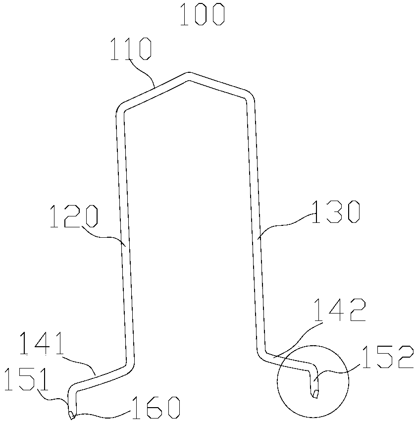
[0074] Such as Figure 1a As shown, the conductor segment 100 according to this embodiment includes a bent portion 110 , a first in-slot portion 120 and a second in-slot portion 130 . In this example, if Figure 1a and 2 As shown, the conductor segment 100 is made of flat copper wire.

[0075] Such as figure 2 and Figure 4a As shown, the bending part 110 includes a first layer section 111, a second layer section 112 and a connecting section 113 connected between the first layer section 111 and the second layer section 112, and the first layer section 111 and the second layer section 112 are arc-shaped. The first in-trough part 120 is connected to an end of the first layer section 111 away from the connecting section 113 , and the second in-trough part 130 is connected to an end of the second layer section 112 away from the connecting section 113 .

[0076] The conductor segment 100 also includes: a first connecting portion 141 and a second connecting portion 142, a first...

Embodiment 2

[0085] Such as Figure 1a As shown, the conductor segment 100 according to this embodiment includes a bent portion 110 , a first in-slot portion 120 and a second in-slot portion 130 . In this example, if Figure 1a and 2 As shown, the conductor segment 100 is made of flat copper wire.

[0086] Such as figure 2 and Figure 4a As shown, the bending part 110 includes a first layer section 111, a second layer section 112 and a connecting section 113 connected between the first layer section 111 and the second layer section 112, and the first layer section 111 and the second layer section 112 are arc-shaped. The first in-trough part 120 is connected to an end of the first layer section 111 away from the connecting section 113 , and the second in-trough part 130 is connected to an end of the second layer section 112 away from the connecting section 113 .

[0087] The conductor segment 100 also includes: a first connecting portion 141 and a second connecting portion 142, a first...


PUM


Abstract

The invention provides a conductor section and a stator assembly with the same, and a motor. The conductor sections are adapted to be inserted into the same slot layer of different stator slots of a stator core; each conductor section is formed in a general U-shaped shape and comprises a bending portion, and a first groove inner portion and a second groove inner portion which are connected to thebending portion separately; the end part of the first groove inner portion is connected with a first welding part; and the end part of the second groove inner portion is connected with a second welding part, wherein the free ends of the first welding part and the second welding part are both provided with chamfering parts. According to the conductor section provided by the embodiments of the invention, the offline is reliable, and the welding is convenient.

Description

technical field [0001] The invention relates to the field of motors, in particular to a conductor segment of a stator assembly, a stator assembly including the conductor segment, and a motor including the stator assembly. Background technique [0002] In the related art, in the hairpin coils of the same layer used in the plug-in stator assembly, the U-shaped head is bent inwardly towards one of the legs to form a bending step, which will make The end of the U-shaped part of the hairpin coil (that is, the hairpin end) becomes higher; in addition, because the bending fillet of the bending step is too small, it is easy to damage the paint skin on the surface of the flat copper wire, resulting in poor insulation. Contents of the invention [0003] The present invention aims to solve at least one of the technical problems existing in the prior art. For this reason, the present invention proposes a conductor section of a stator assembly, the conductor section is reliable off-li...

Claims


Application Information

Patent Timeline
Patent Type & Authority Applications(China)
IPC IPC(8): H02K3/04H02K1/16H02K3/28
CPCH02K1/165H02K3/04H02K3/28H02K2213/03H02K1/16H02K3/40
Inventor 林焕炜游斌齐文明
Owner BYD CO LTD
Learn More