A new type of bus duct with high efficiency and anti-leakage

A busway and anti-leakage technology, applied in the field of busbars, can solve the problems of inability to repair and replace, low use efficiency, complicated connection between the shell and the side plate, etc. Effect

Active Publication Date: 2020-04-21
CHONGQING JINGLI ELECTRICAL APPLIANCE CO LTD
View PDF4 Cites 0 Cited by
  • Summary
  • Abstract
  • Description
  • Claims
  • Application Information

AI Technical Summary

Problems solved by technology

[0004] The technical problem to be solved by the present invention is that the existing housing and side panels are connected in a complicated way, and the interior cannot be easily and quickly repaired and replaced, and the use efficiency is low. Internal repair and replacement issues

Method used


Image

  • A new type of bus duct with high efficiency and anti-leakage
  • A new type of bus duct with high efficiency and anti-leakage

Examples


Embodiment 1

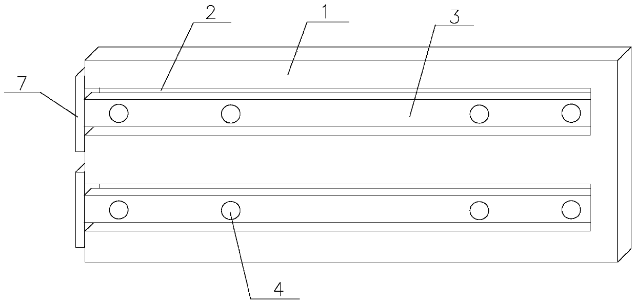
[0028] Such as Figure 1~2 As shown, the new type bus duct with high efficiency and leakage prevention of the present invention includes a bus duct side plate 1, a flame-retardant partition 5, and two parallel first grooves 2 and first grooves 2 are provided on the bus duct side plate 1 One end is in the busway side plate 1, and the other end penetrates through one end of the busway side plate 1. The first groove 2 is provided with a connecting plate 3, one end of the connecting plate 3 is connected to the spring, and the other end of the spring is connected to the first concave The groove 2 is connected at one end in the side plate 1 of the busbar, and the other end of the connecting plate 3 is outside the first groove 2. Under the action of the spring, the connecting plate 3 moves along the line where the first groove 2 is located;

[0029] The connecting plate 3 is provided with a through hole 4 for connecting the flame-retardant partition plate 5, and the through hole 4 is pr...

Embodiment 2

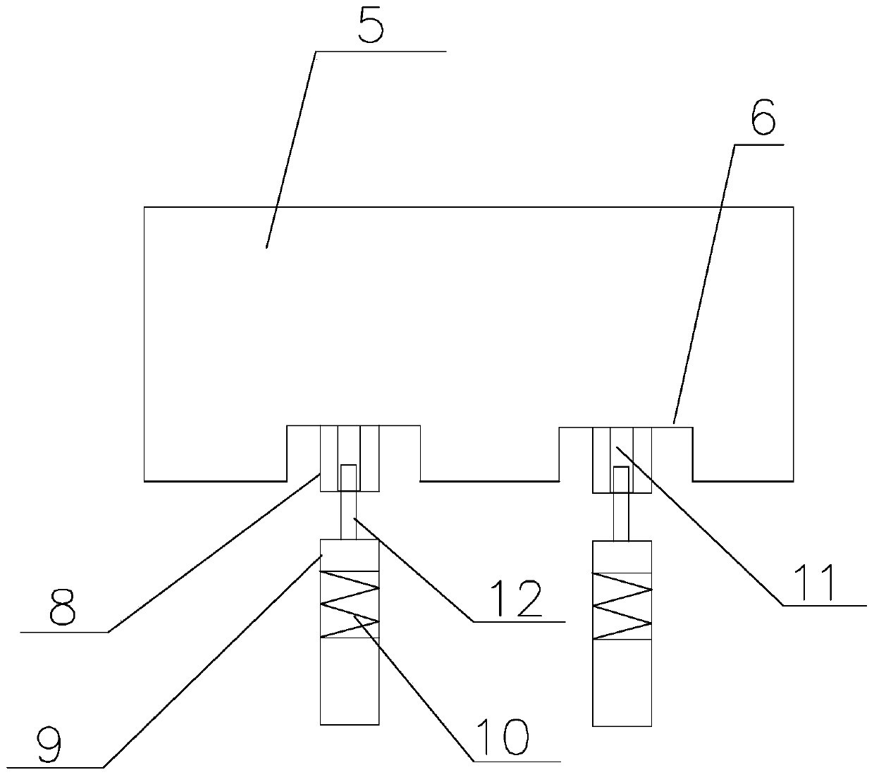
[0032] On the basis of embodiment 1, the middle part of the connecting plate 9 is a spring 10 that can expand and contract along the line where the connecting plate 9 is located. A through groove 11 is provided in the rotating plate 8. The through groove 11 and the connecting plate 9 are on the same vertical straight line. An adjusting rod 12 is connected between the connecting plate 9 and the rotating plate 8. The adjusting rod 12 passes through the thread and the through groove. 11 is connected, and by rotating the adjusting rod 12, the distance between the upper end of the connecting plate 9 and the rotating plate 8 is adjusted.

Embodiment 3

[0034] A new type of bus duct with high efficiency and anti-leakage. The connecting plate 3 is vertically connected with a positioning plate 7 on one end outside the bus duct side plate 1. The positioning plate 7 is outside the bus duct side plate 1, and the positioning plate 7 is in contact with the bus duct side plate 1. An iron absorption layer is arranged on the surface of the, and the positioning plate 7 is fixedly connected with the side plate 1 of the busbar through the iron absorption layer. The width of the second groove 6 is the same as the width of the first groove 2.


PUM


Abstract

The invention discloses a novel efficient and anti-creeping bus duct. Through holes for connecting a flame retardant partition plate are formed in connecting plates, each through hole is internally provided with a screw thread, the connecting plates are driven to move by moving the ends, outside first grooves, the connecting plates, under the effect of springs, the connecting plates are arranged outside the first grooves, and the through holes in the connecting plates are moved to the outsides of bus duct side plates; second grooves corresponding to the through holes correspondingly in the twoconnecting plates are formed in the end, connected with the bus duct side plates, of the flame retardant partition plate, a rotating plate is arranged on each second groove, the upper end of each rotating plate can rotate inside the corresponding second groove along the straight line of the axis of the corresponding second groove, the lower end of each rotating plate is connected with the upper end of the corresponding connecting plate, a screw thread corresponding to each through hole is arranged at the lower end of the corresponding connecting plate, each connecting plate is rotatably connected into the corresponding through hole through the corresponding screw thread, after the connection is finished, the connecting plates slide into the first grooves, and the flame retardant partitionplate is fixed onto the bus duct side plates. When the device can be quick and convenient to maintain and replace during maintenance and replacement, and the using efficiency is higher.

Description

Technical field [0001] The invention relates to the field of bus ducts, in particular to a new type of bus duct with high efficiency and leakage prevention. Background technique [0002] With the emergence of modern engineering facilities and equipment, the electricity consumption of all walks of life has increased rapidly, especially the emergence of numerous high-rise buildings and large workshops. Traditional cables as transmission conductors can no longer meet the requirements in large current transmission systems. The parallel use of multiple cables brings a lot of inconvenience to the installation and connection on site. The plug-in bus duct came into being as a new type of power distribution wire. Compared with the traditional cable, the bus duct fully demonstrated its superiority in high current transmission. At the same time, due to the adoption of new technology and new technology, it greatly reduces The contact resistance and temperature rise at the junction of the tw...

Claims


Application Information

Patent Timeline
Patent Type & Authority Patents(China)
IPC IPC(8): H02G5/06
CPCH02G5/06
Inventor 彭翔田力廖光明
Owner CHONGQING JINGLI ELECTRICAL APPLIANCE CO LTD
Why Eureka
Try Eureka